
Electronic circuits cannot function without a proper power supply and a good power supply ensures stable and reliable circuit performance.
Power supply is one of the most important sections in any electronic system and many electronic circuits need both positive and negative voltage, for example, operational amplifier circuits, audio circuits and analog circuits need dual power supply.
Therefore, a dual power supply circuit design used which provides +15V and -15V at same time.
However, buying a ready power supply may be expensive, so many hobbyists like to build their own power supply.
This article explains a simple transistor based ±15V dual power supply circuit that uses common components, including a transformer, rectifier diodes, capacitors, Zener diodes and transistors
As a result, the circuit gives stable +15V and -15V output and also the circuit can supply about 0.5A current.
Circuit Working:
Parts List:
| Components | Values | Quantity |
|---|---|---|
| Resistors | 330Ω 1W | 2 |
| Capacitors | Electrolytic 1000µF 35V | 2 |
| Electrolytic 100µF 25V | 4 | |
| Semiconductors | Zener Diode 15V | 2 |
| Transistor TIP41C, Transistor TIP42C | 1 each | |
| Bridge Rectifier Diodes 1N4007 | 4 | |
| Transformer Primary 110/220V AC, Secondary 18V-0V-18V 1A | 1 | |
| On/Off Switch AC Mains Switch | 1 | |
| Fuse 0.5A | 1 |
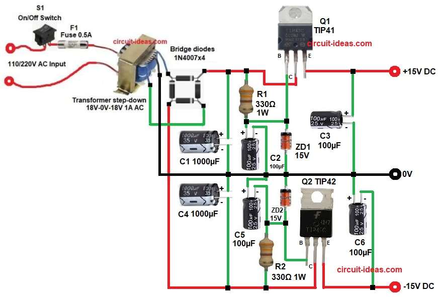
First, AC mains voltage enters the circuit, then AC voltage passes through switch S1 and fuse F1 and the fuse protects the circuit from over current.
Next, the AC voltage goes to the transformer and this transformer steps down the voltage, the secondary of transformer provides 18V AC – 0V – 18V AC.
After that, the AC voltage goes to bridge rectifier made using diodes D1-D4, the bridge rectifier converts AC voltage into pulsating DC voltage.
Then filter capacitors C1 and C3 smooth the rectified voltage and these capacitors remove ripple and produce cleaner DC voltage.
However, the rectified voltage remains unregulated, so Zener diodes ZD1 and ZD2 provide the reference voltage; next, transistor Q1 regulates the positive output voltage, while transistor Q2 regulates the negative output voltage
The Zener diodes provide the reference voltage, allowing the transistors to regulate the output and maintain stable +15V and −15V supplies; in addition, capacitors C4 and C6 provide extra filtering, making the output smoother and more stable
Finally, the circuit gives dual regulated output.
How to Build:
To build a Transistor Based ±15V Dual Power Supply Circuit follow the below connection steps:
- First, start the circuit, by collecting all the circuit parts as in diagram above.
- Then start with transformer primary pins connect to AC mains through switch and fuse and secondary center tap connects to circuit ground.
- After that, other two secondary pins connect to bridge rectifier AC inputs and one end of bridge diode goes to collector of transistor Q1 through filter capacitor C1 positive and resistor R1 and also one end of diode go to negative unregulated DC of collector pin of transistor Q2.
- Now transistor Q1 collector connects to positive unregulated DC, base connects to junction of ZD1 cathode, R1 and capacitor C2 positive and emitter goes regulated +15V output.
- Further, transistor Q2 collector connects to negative unregulated DC, base connects to junction of ZD2 anode , capacitor C5 negative and resistor R2 and emitter gives regulated −15V output.
- Capacitor C1 and C4 connected at unregulated DC input which are the main filter capacitors.
- Finally, capacitor C4 and C6 are the output smoothing capacitors.
Conclusion:
To conclude, this simple and useful transistor-based ±15V dual power supply circuit provides both +15V and −15V outputs, uses basic electronic components, and offers an easy to build, low cost design.
Also, the circuit provides regulated voltage and because of this, it is suitable for many analog and audio circuits.
Finally, this project is good for students, hobbyists and beginners who want to learn power supply design.