Like our previous post on dual power supply, here we learn more about a 15V dual power supply circuit for a preamplifier.
Many electronic circuits need dual voltage supply, for example: operational amplifier circuits, audio circuits and other analog circuits.
These circuits need both positive and negative voltage that is +15V and −15V.
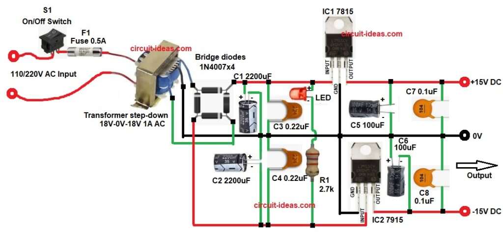
So, this circuit makes a dual regulated power supply which uses two voltage regulator ICs, for example: IC 7815 gives +15V output and similarly IC 7915 gives −15V output.
Overall, this circuit is simple to build and therefore, it is useful for lab power supply and amplifier circuits.
Circuit Working:
Parts List:
| Components | Specification | Quantity |
|---|---|---|
| Resistor | 2.7k 1/4 watt | 1 |
| Capacitors | Electrolytic 2200uF 35V, 100uF 35V | 2 each |
| Ceramic 0.22uF, 0.1uF | 2 each | |
| Semiconductors | Voltage Regulator ICs 7815, 7915 | 1 each |
| Bridge Rectifier Diode 1N4007 | 4 | |
| Transformer step-down secondary 18V-0V-18V 1A, primary 110/220V AC | 1 | |
| Standard LED any color 5mm | 1 | |
| On/Off Switch SPST Switch | 1 | |
| Fuse 0.5A | 1 |
First, the AC mains is applied to the transformer and then this transformer reduces the voltage from 220V AC to 18V AC, then the transformer secondary gives 18V-0-18V AC output, after that this AC voltage goes to the bridge rectifier.
Next, the bridge rectifier is made using four diodes and these diodes convert the AC voltage into pulsating DC voltage.
Then the large electrolytic capacitors C1 and C2 filter the pulsating DC, because of this filtering the output becomes smoother DC voltage and after filtering, this DC voltage goes to the voltage regulator ICs.
The IC 7815 regulates the voltage and gives +15V output and in the same way, the IC 7915 regulates the voltage and gives −15V output.
Also, small capacitors remove high-frequency noise from the supply and at the same time the LED works as a power indicator to show the circuit is ON.
Finally, the circuit gives three output terminals: +15V output, GND and −15V output.
How to Build:
To build a ±15V Dual Power Supply Circuit using 7815 and 7915 ICs follow the below connection steps:
- Start, the circuit by collecting all the components as in circuit diagram above.
- Then, start with transformer primary connect end connect to AC mains through switch and fuse.
- The secondary center tap end connects to ground and the two outer terminals connect to the AC input of the bridge rectifier.
- Then in the bridge rectifier, two diodes connect to the positive output of filter capacitors C1 and C3 and one diode connects to the negative output.
- IC 7815 pin 1 connect to positive DC after filter capacitor, pin2 connect to ground, pin3 goes +15V output.
- IC 7915 pin1 connect to ground, pin2 connects to negative DC line and pin3 goes to -15V output.
- Capacitors C1 and C3 connect in parallel from the input line of IC1 and their negative terminals connect to the ground line.
- Capacitors C2 and C4 connect in parallel between the GND line and the input line of IC2.
- The LED anode and resistor R1 connect in series from the input line of IC1 to the input line of IC2.
- Capacitors C5 and C7 connect in parallel between the output line of IC1 and GND.
- Finally, capacitors C6 and C8 connect in parallel between the GND line and the output line of IC2.
Conclusion:
This ±15V Dual Power Supply Circuit using 7815 and 7915 ICs is a practical solution for circuits that need both positive and negative voltage which provides stable and balanced power for many analog and audio applications.
Moreover, the circuit is easy to assemble and uses easily available components.
Therefore, it is a good choice for electronics hobby projects, testing setups and small laboratory power supplies.
Leave a Reply