
This is 0-30V Transistor Based Variable Power Supply Circuit which gives adjustable output voltage and maximum current is around 2A.
The main power transistor is 2N3055 and it works as series pass transistor in the circuit, since, it is linear type regulator the output is smooth and stable.
Therefore, it is good for lab testing and also, it is useful for electronics hobby work which can power small amplifier, Arduino board, motors and other DC projects; moreover, this circuit is easy to build and all components are easily available in market.
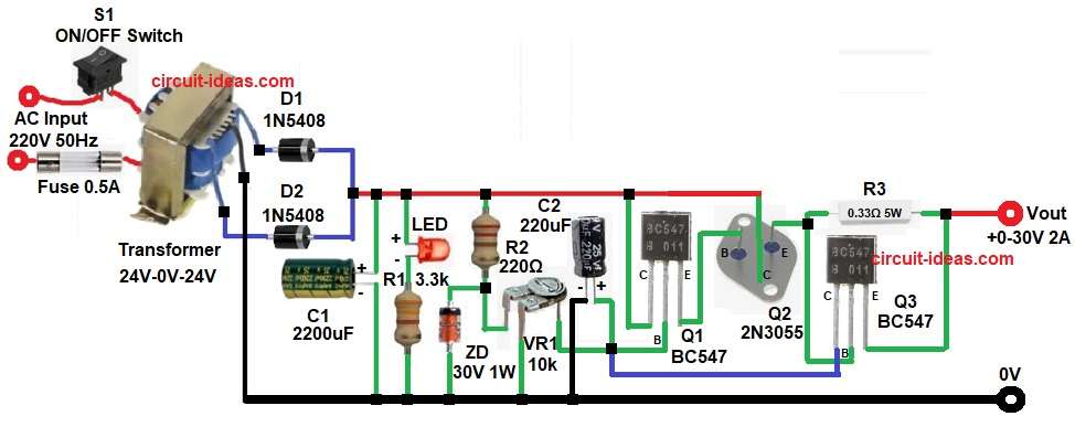
Circuit Working:
Parts List:
| Components | Values | Quantity |
|---|---|---|
| Resistors | 220Ω 1/4 watt, 3.3k 1/4 watt, 0.33Ω 5 watt | 1 each |
| Preset 10k | 1 | |
| Capacitors | Electrolytic 2200uF 25V, 220uF 25V | 1 each |
| Semiconductors | Transistor BC547 | 2 |
| Power Transistor 2N3055 | 1 | |
| Zener Diode 30V 1W | 1 | |
| 5mm LED any color | 1 | |
| Rectifier Diode 1N5408 | 2 | |
| Transformer primary 220V AC 50Hz, secondary 24V-0V-24V | 1 | |
| SPST ON/OFF Switch | 1 | |
| Fuse 0.5A | 1 |
First, the 220V AC mains supply enters the transformer, which steps the voltage down to 24V AC and next, diodes D1 and D2 rectify the AC voltage, converting it into pulsating DC.
After, that the capacitor C1 removes ripple and because of this the DC becomes smooth.
Now unregulated DC voltage is about:
Vdc = Vac × 1.414
= 24 × 1.414
Vdc = 33.9V
However, the diode voltage drop and load ripple reduce the practical DC voltage to approximately 32V, then this unregulated DC voltage supplies the collector of the 2N3055 transistor.
Meanwhile, the control section starts working and the 30V Zener diode gives stable reference voltage.
Preset VR1 adjusts the base voltage of the driver transistor and wen we rotate VR1, the base voltage of Q1 BC547 changes, causing its emitter voltage to change as well.
This emitter voltage then drives the base of Q2 2N3055, thereby controlling the base current of the 2N3055 transistor.
When base current changes the output voltage also changes and therefore, output voltage can adjust from 0V up to nearly 30V.
Formulas with Calculation:
Output Voltage Formula:
Output voltage mainly depends on base-emitter drop and preset setting.
Vout = Vz − Vbe
where,
- Vz is the Zener voltage
- Vbe is 0.7V
So:
Vout = 30 − 0.7
Vout = 29.3V maximum
Practically, maximum Output Voltage is around 28-29V.
Current Calculation:
Emitter resistor R3 = 0.33 ohm
Maximum safe current approx:
I = 0.7 / R
0.7 / 0.33
I = 2.12A
Therefore, the maximum safe current is near 2A.
How to Build:
To build a 0-30V Transistor Based Variable Power Supply Circuit, follow the below connection steps:
- First, collect all required components.
- Then start with transistor Q1 BC547 and connect its collector to unregulated DC, connect base of Q1 to junction of VR1 center pin and positive of capacitor C2 and after that connect emitter of Q1 to base of Q2.
- Now take transistor Q2 2N3055 and first connect its base to emitter of Q1, then connect collector of Q2 to unregulated DC and after that connect emitter of Q2 to base of Q3 and one end of resistor R3.
- Next, take transistor Q3 BC547 and connect its emitter to other end of R3 and to Vout (0–30V), then connect collector of Q3 to junction of VR1 center pin, capacitor C2 positive and base of Q1.
- Now connect capacitor C1 between unregulated DC and Ground.
- After that connect LED anode to unregulated DC and then connect LED cathode to one end of R1 and other end of R1 to Ground.
- Further, connect resistor R2 from unregulated DC and connect other end to upper pin of VR1 and cathode of Zener diode.
- Also, connect Zener diode anode to Ground and also connect lower pin of VR1 to Ground.
- Now do transformer connection: first, connect one primary wire to ON/OFF switch and then connect other primary wire through fuse to mains supply.
- After that connect first 24V secondary wire to anode of diode D1 and then connect third 24V secondary wire to anode of diode D2.
- Finally, connect 0V center tap wire directly to circuit Ground.
Conclusion:
Overall, this 0-30V Transistor Based Variable Power Supply Circuit is simple and with strong design, as it gives adjustable output from 0 to 30V and also its current is up to 2A is possible.
However, efficiency is low because it is linear type supply, but output voltage is clean and stable; so this circuit is very good for bench testing and hobby electronics work.
Additionally, use a large heat sink and connect a high quality transformer to ensure reliable long-term operation.
Therefore, this circuit is an excellent project for beginners and serves as a practical power supply for workshops and electronic repair work.