This 100 Watt Audio Amplifier Circuit using Transistors make sound loud.
It uses transistors to give 100 Watt power to speaker.
Input is small audio signal in which circuit boost and drive big speaker.
Circuit is good for music system, home theater and for party sound.
Circuit Working:
Parts List:
| Category | Description | Quantity |
|---|---|---|
| Resistors (All resistors are 1/4 watt unless specified) | 4.7k | 1 |
| 680Ω | 2 | |
| 47k | 2 | |
| 10k | 2 | |
| 22Ω | 1 | |
| 22Ω 1/2 watt | 2 | |
| 1k 1 watt | 1 | |
| 1.5k 2 watt | 1 | |
| 100Ω 2 watt | 2 | |
| 1Ω 5 watt | 2 | |
| Capacitors | Ceramic 560pF | 1 |
| Electrolytic 1μF 50V | 1 | |
| Electrolytic 4.7μF 50V | 1 | |
| Electrolytic 10μF 50V | 1 | |
| Electrolytic 47μF 50V | 1 | |
| Semiconductors | BJT BC108 | 2 |
| BJT 2N6107 | 2 | |
| BJT 2N3773 | 2 | |
| BJT 2N5294 | 1 | |
| Loudspeaker | 1 |
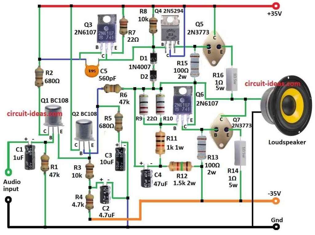
In the above circuit diagram first weak signal become strong by resistor, capacitor and transistors Q1, Q2.
Then signal get more power in middle stage with help of R8, R15 for Q1 and R9 to R13 for Q2 and with this Q4 and Q6 also gives help.
Last stage Q5 and Q7 send strong signal to speaker.
Speaker is with low impedance and amplifier is at high impedance through which driver stage match so speaker is safe.
Circuit gives up to 100W.
Power supply uses positive and negative voltage to about normal 35V.
Formulas:
When making 100W audio amplifier with transistors we should think about:
Output Power:
Pout = Vpeak² / (2 × RL)
where,
- Vpeak is 35V − Vsat (loss in transistor)
- RL is speaker resistance
Power Loss (Heat):
Pdiss = VCE × IC
where,
- VCE is voltage between collector and emitter
- IC is collector current
This help us to know heat for choosing heatsink.
For safe and strong 100W amplifier use better parts and design.
How to Build:
To build a 100 Watt Audio Amplifier Circuit using Transistors follow the below mentioned connections steps:
- Q1 collector go to +35V with resistor R.
- Q1 base take audio input by capacitor C1.
- Q1 emitter join with Q2 emitter.
- Q2 collector goes to +35V.
- Q2 base goes to resistor R6.
Q2 emitter goes to −35V with R3 and R4. - Q3 base connect to capacitor C5.
- Q3 collector goes to Q4 base.
- Q3 emitter goes to +35V.
- Q4 base join Q3 emitter.
- Q4 collector goes to +35V.
- Q4 emitter goes to Q5 base.
- Q5 base join Q4 emitter.
- Q5 collector goes to +35V.
- Q5 emitter goes to speaker by R16.
- Q6 base connect R10 and R11.
- Q6 collector goes to Q7 base.
- Q6 emitter goes to R15.
- Q7 base join Q6 collector.
- Q7 collector goes to speaker.
- Q7 emitter goes to −35V with R14.
- R5 and C3 from Q2 base go to ground.
- Connect C2 positive between R3 and R4 and negative to ground with C3.
- Connect R8 from +35V through diodes D1 and D2 which go to point between R9 and R10.
Safety:
- Use good solder tools.
- Transistors make much heat so we should use heatsink and thermal paste.
- Test first at low volume and then watch for problems.
- Check wires and parts before power ON to avoid short or burn.
Conclusion:
100 Watt Audio Amplifier Circuit using Transistors make weak audio become loud using 3 stages:
Pre-amp (voltage gain), Driver stage, Power output stage
It uses dual polarity power with +35V and −35V and gets hot.
Leave a Reply