A 12V negative voltage regulator circuit gives a stable -12V DC output from AC mains supply, in many electronic applications, we need both positive and negative voltages therefore, this circuit becomes very useful.
This 12V Negative Voltage Regulator Circuit with Zener and Transformer is useful in audio amplifiers, operational amplifier circuits, analog systems and dual power supply projects.
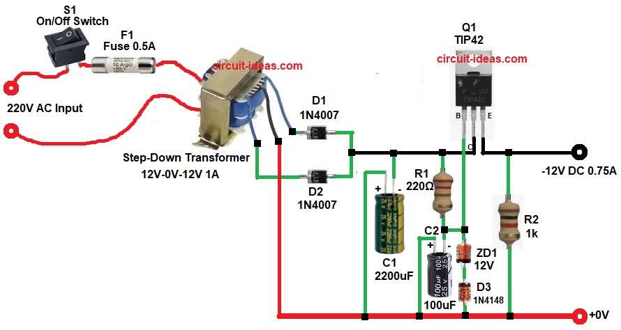
In this design, the circuit uses a step-down transformer, rectifier diodes, filter capacitors, a Zener diode and a TIP42 transistor for voltage regulation, as a result, the circuit gives a clean and regulated -12V output with current up to around 0.75A.
Circuit Working:
Parts List:
| Components | Values | Quantity |
|---|---|---|
| Resistors | 220Ω, 1k 1/4 watts | 1 each |
| Capacitors | Electrolytic 2200uF 25V, 100uF 25V | 1 each |
| Semiconductors | Transistor TIP42 | 1 |
| Heat sink for TIP42 | 1 | |
| Zener Diode 12V | 1 | |
| Diode 1N4148 | 1 | |
| Rectifier Diode 1N4007 | 2 | |
| Step-Down Transformer primary 220V AC Mains, secondary 12V-0V-12V 1A | 1 | |
| Fuse 0.5A | 1 | |
| On/Off Switch SPST Switch | 1 | |
| Output Power Supply -12V DC 0.75A | 1 |
First, AC mains comes into circuit through switch S1 and fuse F1, fuse protects circuit from over current and after this, transformer T1 steps down 220V AC to 12V AC.
Next, diodes D1 and D2 change AC voltage into pulsating DC voltage and since this is negative voltage circuit, diode connection makes negative rectification.
Then capacitor C1 2200uF smooths the pulsating DC, because of this ripple becomes less and so output voltage becomes more stable.
After filtering, resistor R1 gives current to Zener diode ZD1, the 12V Zener keeps reference voltage at -12V and at the same time the capacitor C2 removes noise and improves voltage stability.
Now transistor Q1 TIP42 works as series pass transistor which controls the output voltage and also, it gives higher output current, so circuit can supply around 0.75A load current.
Finally, resistor R2 works as bleeder resistor or minimum load resistor which helps keep output stable.
How to Build:
To build a 12V Negative Voltage Regulator Circuit with Zener and Transformer following steps are required for connections:
- At first, collect all the circuit parts as shown in diagram above.
- Next, start with transformer T1 with primary one side connect AC live input through switch and fuse.
- And primary other side connect to neutral end.
- Next, take secondary side of transformer and connect one side to diode D1 cathode end.
- Middle end of transformer connect to ground 0V.
- Third end of transformer connect to cathode side of diode D2.
- Then take diode D1 and connect anode to transformer upper 12V terminal.
- And cathode is connected to filter section output line.
- Diode D2 anode is connected to transformer lower terminal.
- And cathode is connected to same output line.
- Next, take capacitor C1 negative pin connect to output negative rail.
- And positive pin goes to ground/common line 0V.
- After that take, resistor R1connect one end to transistor collector pin.
- And other end of resistor R1 goes to base of transistor Q1, negative of capacitor C2 and anode of Zener diode.
- Next take, capacitor C2 negative end reference node and positive end goes to ground 0V.
- Then take, Zener Diode ZD1 cathode is connected to transistor base control node and anode is ground through D3 path.
- After that take diode D3 and connect cathode to Zener cathode end and anode goes to ground 0V.
- Next take, transistor Q1 TIP42 base pin connect to junction of resistor R1, capacitor C2 negative and Zener diode anode end.
- Collector pin goes to raw negative DC input and emitter pin goes to regulated -12V output.
- Lastly, resistor R2 one end goes to output -12V line and other end goes to ground 0V.
Conclusion:
To conclude, this 12V Negative Voltage Regulator Circuit with Zener and Transformer gives stable and reliable -12V DC output.
Also, this circuit uses simple and easily available components, transistor TIP42 handles higher current, so this design works well for medium power applications like op-amp circuits, audio preamplifier circuits and analog boards.
Therefore, this circuit is a good choice when clean negative power supply is needed.
Leave a Reply