To begin with, Battery Voltage Level Indicator Circuit using 3 LED is small circuit to show battery voltage with 3 LED.
Here, one LED for low, one for medium and one for full charge, which helps to know battery is good or need charging.
Thus, we can easily make this circuit and use it for a 12V battery or with a small change, a 24V battery.
Also, it uses one chip name LM393 and this chip help to measure voltage correct and then LED light show battery health.
What is a Battery Voltage Level Indicator Circuit using 3 LED:
This simple electronic circuit, known as a 3-LED Battery Voltage Level Indicator, shows battery voltage with LED lights.
Many battery powered devices use this circuit to measure remaining battery charge, allowing users to check the battery status, the circuit also uses different LEDs to display various voltage or battery levels.
How to Build:

Parts List:
| Components | Values | Quantity |
|---|---|---|
| Resistors | 22k 1/4 W | 1 |
| 1k 1/4 W | 1 | |
| Preset 10k | 2 | |
| Capacitors | PPC 100nF | 1 |
| Semiconductors | Zener Diode 6V 1W | 1 |
| IC LM393 | 1 | |
| LEDs 5mm LED Yellow, Green, Red | 1 each | |
| Fuse 50mA | 1 |
How to Build a Battery Voltage Level Indicator Circuit using 3 LED:
- First, collect all parts and be sure all parts work good.
- Next, check again that LM393, LEDs, resistors, potentiometers and Zener diode are same like in circuit plan.
- After that, put the LM393 chip on PCB (board).
- Then connect PCB to battery one wire to positive (+) and one to negative (–).
- Also, connect LM393 pin 4 to negative and pin 11 to positive power.
- After that connect pin 2 and pin 4 to potentiometer P1.
- Next, connect pin 6 and pin 4 to potentiometer P2.
- Now connect resistors and LEDs like in the circuit diagram.
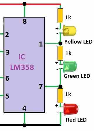
- Then connect yellow LED between pin 2 and pin 7 and connect green LED between pin 6 and pin 7 and red LED between pin 2 and pin 12.
- After that, put Zener diode between pin 8 and pin 4.
- If using another chip like LM358, LM1458 or MC4558 also put resistor for LED 2 and LED 3.
- Also, connect PCBs + and – to power supply and turn ON power and change voltage slowly.
- When voltage is low around 9.5 to 10V, then turn P1 until yellow LED turn ON.
- To check good battery level turn P2 till green LED turn ON.
- Then make voltage higher like 14 to 15V and then turn P2 again until red LED turn ON to show overcharge.
- Lastly, always use good fuse when connecting circuit to keep it safe.
Testing:
- Connect this indicator to real battery to check if it works.
- Always be sure LEDs turn ON correct and are based on battery level.
Warning:
- One should be careful while making and putting the circuit because wrong step can break the indicator.
Formulas:
Below formulas are for Battery Voltage Level Indicator Circuit using 3 LED and yo make this circuit we must do some small math for resistors.
Voltage Divider Resistors:
These resistors give reference voltage to LM393 and they help IC know when to turn ON each LED.
To calculate we use these:
- Battery Voltage (Vbat): Lowest and highest voltage of battery.
- Number of LEDs (N): Here N = 3
- Threshold Voltages (Vt1, Vt2…): The voltage when each LED must turn ON.
LED Current Resistor (Rled):
These resistors stop too much current going to LED and they protect LED from damage.
So, we use this formula:
Rled = (Vbat – Vf) / Iled
where:
- Vbat is the Battery voltage for example 3.7V
- Vf is the LED forward voltage for example 2.0V
- Iled is the LED current to use 10mA to 20mA and here in circuit is 15mA
Example:
Rled = (3.7V – 2.0V) / 0.015A
Rled = 1.13k ohm → use near value like 1.1k ohm
Remember:
This is just simple example and for more detail like pin numbers and full circuit check LM393 datasheet.
Circuit Working:
About the Circuit:
This circuit uses one main chip LM393 a dual op-amp and potentiometer P1 and P2 help check the input voltage level.
How It Works:
P1 sets low battery level around 9.5V to 10V, when battery is full green LED turns ON and P2 sets high level around 14V to 15V and if battery is overcharge then red LED turns ON.
Zener diode give stable voltage to op-amp so it reads correct.
LED Meaning:
Yellow LED = Low battery → Only yellow light ON.
Green LED = Good battery → Yellow + green lights ON.
Red LED = Overcharge → All 3 lights ON (yellow, green, red).
LED Connection:
Wiring LEDs in series keeps the current consistent, preventing them from drawing too much current when we turn ON more than one light.
Also, if using old op-amp like LM358, LM1458, MC4558 we must add resistors with LED2 and LED3 to make circuit work right.
Calibration (Setting it Right):
Use power supply that we can control, turn P1 until yellow LED light is at low voltage and then turn P2 till green LED light at full battery.
Furthermore, increase voltage more, then turn P2 again till red LED light at overcharge level.
Warnings
Connect circuit only to right place in battery setup and always use fuse to stop damage or fire if anything goes wrong.
Final Test:
After setting P1 and P2 connect it to real battery and check if LEDs light up correctly with battery level and this will show us battery status with lights.
Conclusion:
To conclude, Battery Voltage Level Indicator Circuit using 3 LED helps checking battery charge is easy and fast with 3 LED.
The LEDs turn ON at different voltage levels and they show low, medium or full charge by flashing light.