This tutorial teaches us about 35V Dual Output Power Supply Circuit.
This circuit gives plus 35 volt and minus 35 volt.
It is used for audio amplifiers and op-amp circuits.
Circuit uses transformer, bridge rectifier, big filter capacitors.
Output becomes +35V, -35V and ground.
Circuit Working:
Parts List:
| Component | Specification | Quantity |
|---|---|---|
| Capacitors | Electrolytic 4700uF 50V | 2 |
| Ceramic 100nF | 2 | |
| Semiconductors | Transformer 230V Center-tapped 30-0-30V AC | 1 |
| Bridge Rectifier 6A 1N4007 diodes | 4 | |
| Fuse 6A | 2 | |
| Switch | 1 |
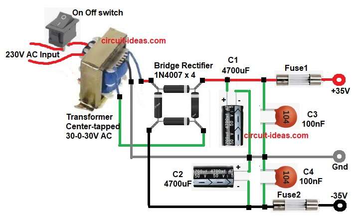
In this circuit the transformer takes 230V AC input and transformer secondary gives two AC wires with center point.
Bridge rectifier converts AC to DC pulsating voltage and after rectifier the capacitor C1 smooths positive rail.
Capacitor C2 smooths negative rail and capacitor C3 and C4 give extra filtering and removes the ripple.
Both the fuse protect both rails from over current.
Center point of transformer becomes ground.
The switch controls the AC input and safely turns the power supply ON and OFF.
So we get three terminals: +35V, GND and -35V.
Formulas:
Formula for DC output after bridge:
Vdc = Vac_rms * 1.414 – (2 * diode_drop)
where,
- Vdc is the final DC voltage after rectifier.
- Vac_rms is the transformer AC RMS voltage.
- 1.414 is square root of 2 used to convert AC to peak.
- diode_drop is voltage loss of one diode, about 0.7V for 1N4007.
- 2 * diode_drop means current passes through two diodes in bridge, so double voltage loss.
So the above formula calculates DC output level after AC is rectified and diodes drop some voltage.
How to Build:
To build a 35V Dual Output Power Supply Circuit follow the below steps for connection:
- Gather all the parts as shown in circuit diagram.
- Transformer primary pin connect to 230V mains input.
- Transformer secondary three wires are two ends and center tap.
- Connect both ends to AC input of bridge rectifier.
- Center tap goes to ground line.
- Bridge rectifier plus pin goes to positive filter capacitor C1.
- Bridge rectifier minus pin goes to negative filter capacitor C2.
- C1 positive pin goes to +35V rail.
- C1 negative pin goes to ground.
- C2 negative pin goes to -35V rail.
- C2 positive pin goes to ground.
- Add C3 across +35V and ground.
- Add C4 across -35V and ground.
- Put FUSE1 in +35V line before output terminal.
- Put FUSE2 in -35V line before output terminal.
- Switch is connected on the AC mains.
Conclusion:
This 35V Dual Output Power Supply Circuit gives stable dual power supply.
It is useful for many analog circuits as its parts are simple and with low cost.
Large capacitors make output clean and smooth.
The circuit is easy to build for beginners.
Leave a Reply