Sound follows us in every moment of our life and wherever we go sound travels with us; so sometimes we need a small electronic circuit that can sense sound and give output.
A sound sensor is useful in many projects like clap switch, voice controlled light, sound activated alarm, toys and automation systems.
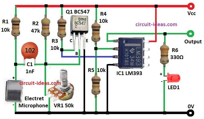
This article explains a Sound Sensor Circuit using IC LM393, microphone, transistor BC547, electret microphone, LED and with few resistors
Circuit Working:
Parts List:
| Components | Values | Quantity |
|---|---|---|
| Resistors | 10k 1/4 watt | 4 |
| 47k 1/4 watt | 1 | |
| 330Ω 1/4 watt | 1 | |
| Potentiometer 50k | 1 | |
| Capacitor | Ceramic 1nF | 1 |
| Semiconductors | IC Comparator LM393 | 1 |
| Transistor NPN BC547 | 1 | |
| Electret Microphone | 1 | |
| LED Red | 1 |
To begin with, the circuit starts with a small condenser microphone, which converts sound into small electrical signals.
These signals are very weak, so the circuit passes them through capacitor C1, then this capacitor C1 blocks the DC component and allows only the AC sound signal to pass.
Then signal goes to transistor Q1 BC547 and this transistor works as amplifier, and then resistors R2, VR1 and R3 give biasing to transistor.
The circuit then feeds the amplified signal to the LM393 comparator IC, then the comparator compares two voltages: the transistor supplies the signal to the non-inverting input (pin 3), while the voltage divider formed by R4 and R5 provides the reference voltage to the inverting input (pin 2).
If the sound signal exceeds the reference level, the comparator drives its output low, since the LM393 has an open-collector output, LED1 glows through resistor R6 whenever the sensor detects sound.
Formulas with Calculations:
Voltage divider at -input pin is with simple formula:
Vref = Vcc * (R5 / (R4 + R5))
where,
- Vcc is 5V
- R4 is 10k and
- R5 is 10k
Vref = 5 * (10k / (10k + 10k)) = 2.5V
So comparator will switch when amplified sound signal crosses 2.5V
Gain of transistor stage approx = Rc / Re
Here,
- Rc = R3 = 10k
- Re is internal emitter resistance around 25mV/Ie.
Hence, with small current gain amplification is enough to drive a comparator.
How to Build:
To build a Sound Sensor Circuit using IC LM393 following are the connections steps:
- First, gather all parts same as in circuit diagram.
- Then electret Microphone one pin goes to ground and other pin go to R1 and C1, R1 is 10k pull up resistor and it connects to Vcc and C1 is 1nF capacitor and it passes audio signal to base of Q1.
- After that, Q1 is BC547 transistor its emitter go to ground, collector go to R3 and base go to VR1 and ground.
- Also, R2 is 47k and it connect between Vcc and base for bias.
- After that, R4 and R5 are both 10k and they make voltage divider and they go between Vcc and ground and middle point go to pin 2 of IC1.
- Further, pin 3 of LM393 connect to collector of transistor.
- Now pin 4 of LM393 go to ground and pin 8 go to Vcc.
- Finally, pin 1 of LM393 is output and this output drive LED1 through R6 330 ohm.
Conclusion:
To conclude, this Sound Sensor Circuit using IC LM393 is simple and with low cost, it uses only few parts and run on 5V supply.
Microphone catch sound, transistor make signal big and then comparator check signal with reference and LED glow when sound is there.
VR1 adjusts the sensors sensitivity, and this circuit enables clap switches, sound alarms, toys and small automation systems.
Leave a Reply