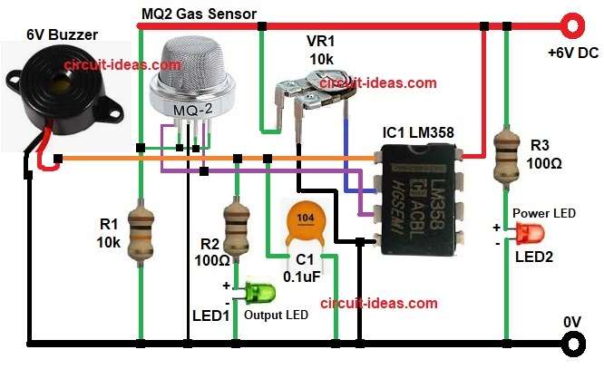
This circuit is for simple Smoke Detector Circuit using IC LM358, as it uses MQ2 gas sensor to sense smoke; also it uses LM358 IC to compare sensor voltage.
Therefore, when smoke is present the buzzer and LED turn ON and, in addition, this circuit is good for beginners.
Circuit Working:
Parts List:
| Components | Quantity |
|---|---|
| Resistors | |
| 10k 1/4 watt | 1 |
| 100Ω 1/4 watt | 2 |
| Preset 10k | 1 |
| Capacitor | |
| Ceramic 0.1uF | 1 |
| Semiconductors | |
| IC LM358 | 1 |
| MQ2 Gas Sensor | 1 |
| 6V Buzzer | 1 |
| LED Red and Green | 1 each |
| 6V DC Power Supply | 1 |
MQ2 sensor gives analog voltage, as if smoke is low then sensor voltage is small and if smoke is high then sensor voltage goes up.
Further, VR1 preset sets threshold level, then R1 resistor keeps input at a fixed level when sensor output is low and after that resistor R2 and R3 limits current to LEDs and protect LEDs from burning.
Now IC LM358 compares sensor voltage with preset voltage and when sensor voltage crosses preset level then LM358 output goes HIGH.
Then buzzer gets power and makes sound, output LED1 also turns ON to show smoke detected and then power LED2 shows circuit ON.
Formulas:
Below is the formula for Smoke Detector Circuit using IC LM358:
Sensor voltage proportional to smoke concentration.
Output voltage formula:
Vout = (Rs / (Rs + RL)) * Vcc
where,
- Vout is voltage across sensor and load.
- Rs is sensor resistance that changes with smoke.
- RL is the fixed load resistor.
- Vcc is the main supply voltage.
The above formula shows simple voltage divider action in MQ2.
When smoke changes Rs, the ratio changes and Vout changes and then LM358 reads this changing voltage to detect smoke.
How to Build:
To build a Smoke Detector Circuit using IC LM358 following are the steps one needs to follow:
- First, gather all the parts as shown in circuit diagram.
- Next, MQ2 sensor 1st, 5th and 6th leg connect to pin 3 of IC1, MQ2 sensor 2nd and 4th leg connect between +6V DC and resistor R and MQ2 sensor 3 leg connect to GND.
- Then connect 10k preset between Vcc and GND and connect preset middle pin to LM358 inverting pin 2.
- After that, LM358 pin 8 goes to Vcc, LM358 pin 4 go to GND and LM358 pin 1 gives output A.
- Also, connect LM358 output pin 1 to buzzer on end and other end of buzzer goes to GND.
- Now, connect anode of LED1 output with R2 resistor to show smoke and cathode of LED1 output goes to GND
- Further, connect anode of power LED2 with resistor R3 from positive supply and cathode of LED2 connect to GND
- Finally, place C1 capacitor from pin 1 and ground for stability.
Conclusion:
Overall, this Smoke Detector Circuit using IC LM358 is simple and with low cost, as it detects smoke quickly; also MQ2 sensor and LM358 make design easy.
Furthermore, it is useful for small rooms, labs, kitchens and projects and is easy to build for hobby and learning.

Leave a Reply