This is Simple 9V Transistor Inverter Circuit using 9V battery.
The circuit is very small and easy to make which helps to understand DC to AC working.
Only few low cost parts are used and its output power is very low.
It is only for testing and learning.
This circuit is useful for students and beginners.
Circuit Working:
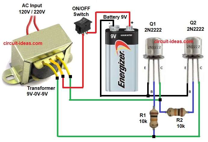
Parts List:
| Component Name | Specification | Quantity |
|---|---|---|
| Resistors | 10k 1/4 watt | 2 |
| Semiconductors | Transistors 2N2222 | 2 |
| Battery 9V DC | 1 | |
| ON/OFF Switch SPST Switch | 1 | |
| Transformer 9V-0V-9V Primary, 120V or 220V Secondary | 1 |
The battery gives 9V DC power and the switch is used to turn circuit ON and OFF.
Transformer primary has center tap and its center tap is connected to battery positive.
Two transistors work in push pull way like:
When Q1 is ON then Q2 is OFF.
And when Q2 is ON then Q1 is OFF.
This ON and OFF action makes AC current in transformer.
Transformer increases the voltage.
AC output comes from secondary side and this output is not pure sine wave.
It is square wave type AC.
Formula with Calculation:
Below is the formula for Simple 9V Transistor Inverter Circuit:
Battery voltage = 9V
Primary voltage per half winding = 9V
If transformer is 9-0-9 / 220V
Turns ratio = 220 / 9 = 24.4
Output voltage approximately = 9 x 24.4
Output voltage = about 220V AC
Base resistor value = 10k
Base current = 9V / 10000
Base current = 0.9 mA
This current is enough for small transistor switching.
How to Build:
To build a Simple 9V Transistor Inverter Circuit follow the below steps for connection:
- Take all parts same as circuit diagram.
- Transformer center tap connect to battery positive using switch.
- Both side of transformer primary connect to collector of Q1 and Q2.
- Emitter of Q1 and Q2 connect to battery negative.
- Base of Q1 and Q2 connect to R1 and R2 resistors.
- Other end of R1 and R2 connect to collector of Q1 and Q2.
- Battery negative is common ground.
Conclusion:
This Simple 9V Transistor Inverter Circuit is good for basic learning.
Circuit uses very parts and its working is easy to understand.
Output power is very small but it is not for real AC appliance use.
Best for students, practice and experiment purpose.
References:
Getting 9v output from 9v battery with transistor and resistor
Leave a Reply