A power supply is vital in electronics because most circuits require a stable DC voltage.
Since the mains supply provides AC voltage, the power supply must convert this alternating current into the direct current that sensitive components rely on to function
This Transistor Based 5V Linear Power Supply Circuit gives regulated 5 volts DC and it uses simple components, gives high current and is useful for labs and projects.
Circuit Working:
Parts List:
| Components | Values | Quantity |
|---|---|---|
| Resistors | 150Ω, 220Ω | 1 each |
| 100Ω | 2 | |
| Preset 100Ω | 1 | |
| Capacitor | Electrolytic 4700uF 25V | 1 |
| Semiconductors | Transistor TIP3055 | 1 |
| Transistor BD139 | 1 | |
| Bridge Diodes 1N4004 | 4 | |
| Diodes 1N4148 | 4 | |
| Transformer 6.3V AC 1A to 2A | 1 | |
| Heat Sink For TIP3055 | 1 |
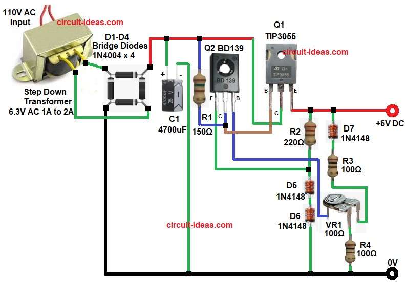
At the start, the circuit uses a step-down transformer, and AC mains enters the transformer, then the transformer reduces the voltage to 6.3V AC.
After that the bridge rectifier changes AC into pulsating DC and then capacitor C1 removes the ripple and so the DC becomes smooth.
Now transistor Q2 controls the voltage reference, while diodes D5 and D6 generate the reference voltage, and VR1 adjusts the output voltage.
After this the transistor Q1 TIP3055 works as series pass transistor which carries high current load, so the voltage stays stable.
Finally, diode D7 protects the output from reverse voltage, resulting in a regulated 5V DC output.
How to Build:
To build a Transistor Based 5V Linear Power Supply Circuit follow the below connection steps:
- First, start the circuit by collecting all the parts as shown in circuit diagram.
- Then start with transformer primary end connected to 110V AC mains and secondary end connected to bridge rectifier input D1-D4.
- After that, capacitor C1 positive pin connected to rectifier positive and negative pin connected to ground.
- Now transistor Q1 TIP3055 base connected between to R2 and collector of Q2, collector connected to unregulated DC and emitter gives regulated 5V output.
- Also, transistor Q2 BD139 base pin connected to VR1 center pin, collector connected to R1 and base of transistor Q1 and emitter connected to anode of diode D5.
- Further, diodes D5 and D6 connected in series for reference voltage.
- At last, diode D7, resistor R3, VR1 and resistor R4 connected in series from 5V positive supply to GND.
Conclusion:
To conclude, this Transistor Based 5V Linear Power Supply Circuit is simple and useful project, also, it is easy to build as it gives stable output.
Transistor TIP3055 handles high current well and with proper heat sink it works reliably and therefore, this circuit is very useful for electronics projects and is good for beginners.

Leave a Reply