This circuit is for 6V Battery Backup Power Supply Circuit using 7805 which gives stable output and also charges a 6V battery.
When main power is ON, then circuit gives regulated supply and charges the battery, when power goes OFF then battery gives backup automatically.
This circuit is useful for small electronics, emergency lights and for low power devices.
Circuit Working:
Parts List:
| Components | Values | Quantity |
|---|---|---|
| Resistors (All resistors are 1/4 watt) | 270Ω, 47Ω, 680Ω, 330Ω | 1 each |
| Capacitors | Electrolytic 2200µF 25V, 33µF 25V, 100µF 25V | 1 each |
| Semiconductors | IC 7805 Voltage Regulator | 1 |
| Bridge Diodes 1N4007 | 4 | |
| Diodes 1N4007 | 3 | |
| Any standard LED as indicator | 1 | |
| Transformer primary 220V AC, Secondary 0V-9V 1A | 1 | |
| Switch On/Off Switch | 2 | |
| 0.5A Fuse | 1 | |
| Battery 6V Rechargeable Battery | 1 |
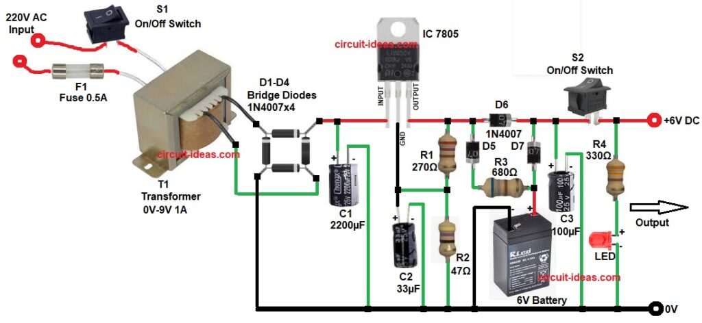
The circuit starts with AC mains comes into transformer and this transformer converts 220V AC to 9V AC, then bridge rectifier D1 to D4 converts AC to DC and capacitor C1 filters the DC and removes ripple.
Now DC goes into IC 7805 and this IC gives regulated 5V output with diode D6 increases voltage drop slightly and helps to get near 6V output for battery charging.
Resistors R1 and R2 with capacitor C2 help in stability and noise filtering, diodes D5 and D7 control charging path and protect battery from reverse current.
When AC power is present then circuit gives output and charges battery B1 through resistor R3 and when AC fails then battery supplies power through diode D7 to output.
Capacitor C3 smooths the output and LED with resistor R4 shows output status (power ON indicator).
Formulas with Calculation:
Below are few formulas with calculation for LED resistor and for Battery Charging Current:
- LED Resistor formula:
R = (V – Vf) / I
R = (6V – 2V) / 0.01A
R = 4 / 0.01 = 400Ω
In out circuit we have used standard R4 value of 330Ω.
2. Battery Charging Current formula:
I = V / R
I = 6V / 680Ω
I = 8.8mA
Here in this circuit the battery charging is slow, but its safe.
How to Build:
To build a 6V Battery Backup Power Supply Circuit using 7805 follow the below connection steps:
- First, start by gathering all the circuit parts as in diagram above.
- Then connect transformer primary in parallel with S1 switch an F1 fuse for protection.
- Secondary side connect to bridge rectifier input D1-D4.
- Connect rectifier output to capacitor C1 with positive side to pin input of 7805 and negative to GND.
- Then connect pin ground to common ground of the circuit 0V.
- Connect pin output line to 6V DC output with diode D6 and S2 on off switch series with output.
- Connect resistor R1 and resistor R2 from output pin of IC and GND.
- Connect capacitor C2 positive from GND pin of IC and negative side goes to GND.
- Connect diode D5 anode from output pin and connect cathode to resistor R3 one end and other end connect between diode D7 anode and positive of battery 6V.
- Connect battery positive through resistor R3 and diode D7 and negative of battery goes to common GND.
- Connect capacitor C3 positive from output pin of IC and negative end of C3 goes to GND.
- Connect on off switch S2 in series with one end between capacitor C3 and resistor R4 at output of +V.
- Finally, connect R4 resistor from output of 6V in series with anode of LED and cathode of LED goes to GND.
Conclusion:
This 6V Battery Backup Power Supply Circuit using 7805 is simple, easy and with low cost, as it gives stable output and automatic battery backup.
It is easy to build, good for beginners, where we can use it for small electronics and emergency systems.
The circuit also protects battery and improves reliability.
Leave a Reply