70 Watt Audio Amplifier Circuit teaches us about one amplifier circuit, which makes sound louder using special parts call MOSFETs which is the type of transistor.
Why this transistor is good for amplifier:
- Can make radio sound which goes up by using small signal to control big signal.
- Does not waste too much power by itself.
- Can handle loud sound with strong signal.
Note: This circuit is little hard to make than the other projects.
Circuit Working:
Parts List:
| Components | Quantity |
|---|---|
| Resistors (All resistors are 1/4 watt unless specified) | |
| 47k | 1 |
| 240Ω | 1 |
| 27k | 1 |
| 220Ω | 1 |
| 22k | 2 |
| 1k | 2 |
| 1.4k | 2 |
| 3.3k | 2 |
| 100Ω | 2 |
| Preset 1k | 1 |
| Capacitors | |
| Ceramic 270pF | 1 |
| Electrolytic 10μF 25V | 2 |
| Electrolytic 1000μF 40V | 2 |
| Semiconductors | |
| Transistors BC547 | 2 |
| Transistors BC560, BC550 | 2 |
| IC TL071 | 1 |
| MOSFETs IRF9530, IRF530 | 2 |
| Zener Diode 400mW 15V | 2 |
| Speaker 4Ω to 8Ω | 1 |
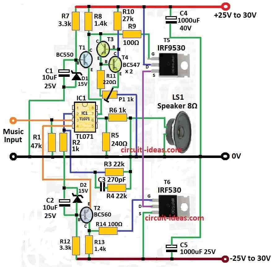
This audio amplifier uses one TL071C op-amp and two MOSFETs: IRF9530 and IRF530, it can also give 45W power to 8 ohm speaker or 70W to 4 ohm speaker.
Here, design come from Siliconix application which have voltage change on two resistors and these resistors connect in parallel to op-amp power.
Also, to work good the MOSFETs must go on heatsink and this heatsink should be minimum 1k/W thermal resistance.
When play with 8 ohm speaker and 10W power sound distortion should be max 0.2% at 20 Hz and amplifier efficiency should be 70%.
Therefore, power supply for this circuit is ±30V and it gives 45W to 8 ohm and 70W to 4 ohm speaker.
Important: This amplifier does not have short circuit protection; so be careful every time before turning ON, check speaker is connected properly to avoid damage.
Formula:
To calculate how much heat (power) MOSFETs to make then we should use this formula:
PD = VDS × ID
where:
- PD is power loss in MOSFETs heat.
- VDS is voltage from drain to source.
- ID is current from drain.
Load Line:
Load line help to find amplifiers Q point and how much output swing is possible.
Gate Drive Voltage:
To fully turn ON the MOSFETs calculate gate voltage using threshold voltage (Vth) and give extra voltage for full ON.
Output Swing:
Also, be sure amplifier can give full peak-to-peak voltage without clipping the cutting sound.
Actual Circuit Things:
Heat Control:
First, put heatsink on MOSFETs to remove heat properly.
After that, use feedback like emitter resistor or feedback resistor to make sound better and reduce distortion.
Protection Circuit:
Then add protection for MOSFET and other parts from too much current or voltage.
Hence, to build good MOSFET output part for power amplifier we need things like low distortion, high efficiency and reliable working.
How to Build:
To build a 70 Watt Audio Amplifier Circuit follow the below steps for connections:
- First, take all parts WE need and look at the circuit diagram like schematic and collect them.
- If using PCB follow the layout from schematic and if using breadboard be sure it is having enough space for all parts.
- Next, put TL071C op-amp on board as shown in schematic and watch carefully the two resistors in parallel that connect to op-amps power supply.
- After that, put MOSFETs on heatsink which is the thermal resistance minimum 1k/W and connect them same as in circuit diagram and check position is correct.
- Then follow the schematic and connect all resistors and capacitors and use correct resistor values for good result.
- Now, give power to the circuit with ±30V at the right points and before turning ON look again and all wires and parts should match the schematic.
- Also, we can use 8Ω or 4Ω speaker as per our choice and connect it to output and turn ON power supply and look and listen carefully.
- After that, use signal generator to send audio in and listen from speaker and slowly increase input and watch how circuit works and check for noise or bad signs.
Be Careful:
- This amplifier have no short circuit protection.
- Always connect the speaker correctly before turning the circuit ON.
- Safety is most important if we are not sure then ask someone who knows electronics.
Conclusion:
To conclude, 70 Watt Audio Amplifier Circuit can change based on what we want like more power, better sound etc; also many engineers and hobby people like to build this type of circuit for learning and fun.
Leave a Reply