Think heatsink like small radiator for our devices which help keep cool.
Heatsink Temperature Protection Circuit is like safety man for that small radiator, as it got small sensor by always checking heatsink heat.
Also, if too hot like one have got fever then this circuit does something, as it maybe a stop power or maybe like start fan to cool down.
Hence, by this way too much heat will not harm the device itself.
Circuit Working:
Parts List:
| Components | Values | Quantity |
|---|---|---|
| Resistors | 10k 1/4 watt | 2 |
| 1k 1/4 watt | 2 | |
| Preset 1M | 1 | |
| Thermistor NTC 4.7k | 1 | |
| Capacitors | Ceramic 0.01µF | 1 |
| Semiconductors | IC 555 | 1 |
| Transistor BC547 | 1 | |
| Diode 1N4007 | 1 | |
| Reset push button | 1 | |
| Buzzer | 1 | |
| Relay 12V | 1 |
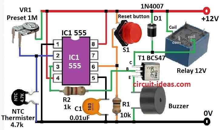
This circuit help protect the power transistor from too much heat and when heatsink get too hot it stops the power to the transistor and when cool again its power come back.
Furthermore, it uses NTC thermistor to feel the heat and also have buzzer and reset thing.
Here, the main chip is 555 IC which works like heat switch and pin 2 of chip connect to VR and thermistor and they decide how much voltage will connect to pin 2 depending on heat.
Also, NTC thermistor have high resistance when cool but when hot its resistance go down.
Pin 6 check voltage too but if it sees more voltage than pin 2 then it reset chip and stop output, then power comes to circuit through NC side of relay so power is there when relay is OFF.
VR1 control how thermistor act and it help keep pin 2 voltage high when cool and when amplifier inside get hot thermistor resistance go low and then pin 2 voltage also goes low.
That make output go high and transistor T1 turn ON and relay also turns ON indicating buzzer to make sound.
Therefore, relay then cut power to circuit board and when things cool down again the relay turns OFF by itself.
Lastly, just put thermistor near heatsink of transistor and use VR1 to set when relay will turn ON from heat.
Formulas:
This formula help to calculate NTC for heatsink heat safety, as this NTC change resistance when hot or cold.
For highly accurate measurements, engineers use the Steinhart–Hart formula, although it is difficult to calculate.
For normal applications, people use the simpler Beta coefficient method, which shows how much the NTC thermistor resistance changes for every 1°C change in temperature.
Below is the simple formula:
Beta = (ΔR / Rref) * (100°C) / ΔT
- Beta is how sensitive NTC is usually negative like -3.5%/°C meaning resistance go down when hot
- ΔR is change in resistance R – Rref
- Rref is resistance at normal temp usually 25°C as written in datasheet
- ΔT is how much temperature change T – 25°C.
Applying the Coefficient of Beta:
How to use Beta to find NTC resistance at any temp:
First, choose the temp one want to check (T).
Then find how much hotter or colder than 25°C it is:
ΔT = T – 25°C
Multiply Beta × ΔT and then divide by 100:
(Beta × ΔT) / 100
This give % change in resistance.
Apply this % to Rref to get new resistance at temp T:
R = Rref ± (Rref × (Beta × ΔT) / 100)
If Beta is negative then resistance goes down when hot.
Note:
Beta method is just an estimate but for super exact result better to check NTC datasheet chart or table.
How to Build:
To build a Heatsink Temperature Protection Circuit below mentioned are the steps for connections:
- First, connect NTC thermistor and VR1 together like voltage divider and join this to pin 2 of 555 IC.
- Then connect pin 6 of 555 IC to some fixed voltage this will help reset IC when needed.
- Join pin 7 to pin 6 and connect pin 5 to pin 8.
- Now connect pin 4 to pin 8 through a resistor.
- Now pin 1 connects to ground and pin 3 connects to base of transistor T1, also T1 emitter connects to ground.
- After that, collector of T1 joins to one side of relay coil and other side of coil connects to VCC.
- Also, relays NC (normally connected) connect to power on the circuit board and then put diode across relay coil this save T1 from voltage spikes when relay turn OFF.
- Put buzzer in parallel with 12V relay will beep when relay turn ON.
Note:
- This is just simple setup, maybe one will need extra parts based on what components its uses; but be sure all parts and power supply are good for the circuit with right voltage and current.
Conclusion:
Overall, Heatsink Temperature Protection Circuit is very important part for electronics, as it watches the heat if things get too hot and it takes action to cool down or stop power.
Also, this way the electronic parts stay safe and work good for long time.
Leave a Reply