Just think like water pipe filling bucket.
Normal circuit is like set water pressure voltage and hope the bucket fills good, but with LED this Simple LED Constant Current Circuit is like smart nozzle.
It keep water flow current same even if pressure changes a little and this way LED light up nice and live longer.
Circuit Working:
Parts List:
| Components | Values | Quantity |
|---|---|---|
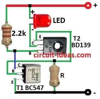
| Resistors | 2.2k 1/4 watt | 1 |
| R (see the text) | 1 | |
| Semiconductors | Transistor BC547 | 1 |
| Transistor BD139 | 1 | |
| LED any 5mm, 20mA | 1 |
This LED constant current circuit is very simple, it only uses 2 transistors, 2 resistors and 1 LED, as it work with input voltage from 2V to 24V so it can run many types of LED even big one up to 5W power.
For T2 transistor we can use BC547 if we use small LED of 20mA, but for big LED it is better to use BD135, BD137 or BD139.
When voltage goes more than 2V then T2 transistor give more current and then T1 also turn ON more; and this make T1 pull voltage down and T2 slow down again so current does not go too high.
Also, this make current stay same always and LED shine good and does not burn.
Example: For 20mA LED resistor R is around 30 ohm.
Some voltage and current example for normal red LED is as follows:
Formulas:
1. How to find value of resistor R:
We can find resistor R using this simple formula:
R (ohm) = 0.6 / I (mA)
where:
- R is resistance in ohms Ω
- I is current in milliamps mA
- 0.6 fixed value used in formula
Example:
If current is 20mA then:
R = 0.6 / 0.02 = 30 ohm
So resistor R is 30 ohm.
This formula is easy and good for small circuit or beginner electronics.
2. How to find resistor power:
The power a resistor uses is called power dissipation and we can also measure it.
Formula: P (W) = I² (A) × R (Ω)
where:
- P is power in watts W
- I is current in amps A
- R is resistance in ohms Ω
This tell us how hot resistor will get.
More current or more resistance = more heat.
If resistor is too small it can burn or break other parts, so always check power before using resistor in actual circuit.
How to Build:
To build a Simple LED Constant Current Circuit we need to follow the below mentioned steps:
Select LED:
- First, choose LED based on how much power and current we want and be sure LED voltage drop is between 2V to 24V.
Find resistor R:
- Next, check LED forward current (I) and then use this formula: R = 0.6 / I (mA) example: If LED is 20mA then R is about 39 ohm.
Build circuit:
- Then connect all parts like in the circuit diagram with power supply (+) connects to collector of T1
- Emitter of T1 connects to LED anode the positive le and LED cathode negative leg connects to collector of T2
- Now base of T1 connects to one side of resistor R and base of T2 connects to middle point of 2.2k resistor
- Emitter of T2 connects to power supply (–)
Turn ON power:
- Give voltage between 2V to 24V.
Check if working:
- Be sure the LED turns ON and check if current stays same and even when voltage changes.
Note:
- Be careful when making the circuit and handle all parts safely and test properly.
Conclusion:
A Simple LED Constant Current Circuit is very important part in LED light system, as it give stable and fixed current to LED so LED work good and live long.
When the current remains constant, the LED does not get damaged and the brightness stays the same and this is why people use this circuit in many types of LED lights.
Some circuits use just resistor and some use more complex regulator, but all do the same job and keep current steady; as a result, this help LED work better and more reliable.
Leave a Reply