This post shows very easy way to make Simple Automatic Battery Charger Circuit using One Transistor and with few parts.
Also, this circuit charges battery by itself like small machine, as it uses only one transistor, one resistor and one LED.
Furthermore the circuit is good for charging 9V battery where LED shows when charging; but this is basic charger with no special protection and is best for simple charging only.
Circuit Working:
Parts List:
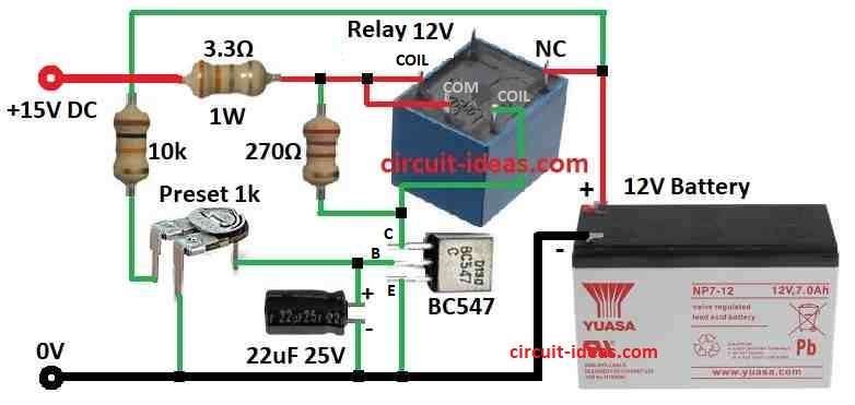
| Components | Values | Quantity |
|---|---|---|
| Resistors | All resistors are 1/4 watt unless specified | |
| 10k 1/4 W | 1 | |
| 270Ω 1/4 W | 1 | |
| 3.3Ω 1W | 1 | |
| Preset 1k | 1 | |
| Capacitor | Electrolytic 22µF 25V | 1 |
| Semiconductors | Transistor BC547 | 1 |
| Relay 12V | 1 | |
| Battery 12V | 1 |
To begin with, this is very simple auto battery charger, which use only 6 parts and work with 12V plug pack with no load voltage with 15V+ is normal.
Relay and transistor are not important but just set 1k preset to turn OFF relay at 13.7V.
Hence, to make voltage better replace 10k resistor with 12V Zener; so use two 6V Zeners or mix with 0.6V diode.
Plug pack current can be:
- 100mA for 1.2Ah battery
- 500mA for 7Ah battery
- 1A for big battery
This charger is for keeping charge and not to fast charge, so current is not very important.
If battery is in use charger also powers the load and for dead battery the charging current should not go over 100mA.
Most 12V plug packs give 15 to 16V with no load and this helps charging without overheating.
To setup:
To test voltage drop put 100 ohm 2W resistor on battery, then charger will turn ON again when voltage drops to 12.5V and about.
This ON/OFF point is not fixed because the hysteresis and the transistor load show it.
In addition, the 22 µF capacitor reduces relay chatter and stabilizes the circuit during charging and voltage fluctuations.
When voltage goes up and current goes down, near cut-off relay may make noise but capacitor can fix this.
To make more gap between ON and OFF then add 270 ohm across relay coil and this need more current to turn ON relay so preset must adjust again.
Therefore, the circuit does not require a diode across the relay because the transistor never turns fully OFF, so the relay does not generate an EMF spike.
Formulas:
Voltage Divider Formula:
Vout = Vin × (R2 / (R1 + R2))
where:
- Vout is the voltage at transistor base
- Vin is the power supply voltage
- R1 and R2 is the resistor values
Important Information:
This circuit has no safety with no heat protection and with no current limit, so in actual circuit good battery charger must have these for safety.
Without it, the battery can suffer damage or receive excessive charge.
To know how this circuit works exactly we need to check all part values and relay wiring and best idea for this circuit is to use proper ready-made battery charger for safe charging.
How to Build:
To build a Simple Automatic Battery Charger Circuit using One Transistor follow the below mentioned steps:
Connection of transistor, resistor and capacitor:
- Connect 1k preset in series with transistor base, connect transistor collector to one side of relay coil and transistor emitter to battery negative (–).
- Connect 22uF capacitor from transistor base to ground.
Connection of Relay:
- Connect other side of relay coil to battery positive (+).
- Connect 10k resistor in series with relay coil and also connect 270 ohm resistor across relay coil.
Notes:
- Working with electricity is risky, so if not sure ask help from someone who knows electronics.
Conclusion:
To conclude, this Simple Automatic Battery Charger Circuit using One Transistor is very easy circuit, as this is good for small batteries like 9V which shows charging status.
Also, this circuit have no safety features with no overcharge stop or voltage control; but it is easy to build with good for basic use only.
Leave a Reply