This post for Free Energy From Air Circuit uses free energy from air, whose idea is simple as air is full of radio waves.
When radio is ON we can hear static and even in empty place, so if we make strong power setup then air can give us endless energy.
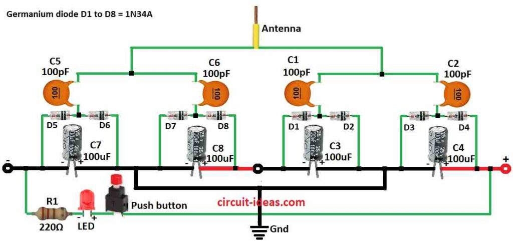
Furthermore, circuit uses antenna, a good crystal diode like germanium and a capacitors to show how we get power from air; as its not a power full house but shows idea how it works.
Circuit Working:
Parts List:
| Components | Values | Quantity |
|---|---|---|
| Resistor | 220Ω 1/4 watt | 1 |
| Capacitors | Ceramic 100pF | 4 |
| Electrolytic 100μF 25V | 4 | |
| Semiconductors | Germanium diodes 1N34A | 8 |
| LED Red 5mm 20mA | 1 | |
| Antenna | 1 | |
| Push button switch | 1 |
Find good antenna, any material can be antenna, here antenna with big roof one used which works well, as any antenna can work but bigger is better and antenna size and height is also important.
Also, make strong ground connection and we can use home ground wire or put metal stick in wet soil.
Moreover, this circuit uses many parts like diodes D1 to D8 and capacitors C1 to C8, as capacitors can keep electric energy in electrostatic field and germanium diodes let current go only one way.
Therefore, antenna catches radio waves, microwaves and light waves from air and then energy goes through diodes and maybe turn into DC current.
After that, the capacitors store this current.
Also, a simple switch in circuit are resistor R1 and push button and when we press LED may light which means power flows; but energy from air is very small which is not enough to run house, machine or LED long time.
Free Energy From Air Circuit Advantages:
- It is an cheap, clean and safe energy, hence, there is no smoke or bad gas.
- This circuit has a strong power from high energy branch and it makes power with no pollution.
- Also, it is easy to build and fixes with simple part, and it is pure with endless power which might be from graphene
Formulas:
Energy from air is very small but we can still build antennas to catch waves like radio or microwave.
1. Antenna Size and Shape:
To make antenna for one frequency (f in MHz) we can use this formula:
λ = c / f
where,
- λ is the wavelength in meters
- c is the speed of light of 299,792,458 m/s
Then we make antenna half that size:
Dipole antenna = λ / 2 meters
Note:
This is simple formula and other antenna types have more hard calculations.
2. Capacitor Selection:
To store energy choose capacitor by this formula:
E = 1/2 * C * V²
where,
- E is the energy in joules
- C is the capacitance in farads and
- V is the voltage
3. Diode Selection:
Pick diode based on voltage and current from antenna.
Important:
Check diodes forward voltage drop and current limit.
How to Build:
To build a Free Energy From Air Circuit follow the below steps for connections:
- First, gather all parts as shown in circuit diagram.
- Next, connect one side of C1 to middle point of D1 anode and D2 to cathode and connect D1 anode to C3 negative and D2 cathode to C3 positive.
- Then connect one side of C2 to middle point of D3 anode and D4 to cathode.
- After that, connect D3 anode to C4 negative and D4 cathode to C4 positive.
- Also, connect one side of C5 to middle point of D5 anode and D6 to cathode, and then connect D5 anode to C7 negative and D6 cathode to C7 positive.
- Now connect one side of C6 to middle point of D7 anode and D8 to cathode and then connect D7 anode to C8 negative and D8 cathode to C8 positive.
- Next, connect antenna to the common points of C1, C2, C5, C6 and then connect ground to common points of C3, C4, C7, C8.
- Put LED across the final output of negative and positive in series with resistor R1 and push button and then connect circuit ground to real ground and use deep copper rod in soil.
Conclusion:
To conclude, one electron must pass both low and high energy sides for division to work.
Right now free energy is small and is not enough to power whole house, but this simple Free Energy From Air Circuit can collect radio wave energy.
Therefore, after collecting we can maybe power small things at home.
Leave a Reply