As name say this Amplifier Speaker Turn-On Delay Circuit wait few seconds before connecting speaker to amplifier.
When amplifier is first turn ON then big “thump” noise can happen and this delay stop that bad sound.
Circuit Working:
Parts List:
| Components | Values | Quantity |
|---|---|---|
| Resistors | 33k 1/4 watt | 2 |
| 1k 1/4 watt | 1 | |
| Capacitors | Electrolytic 100μF 25V | 2 |
| Semiconductors | Transistor BC547 | 1 |
| Diode 1N4007 | 2 | |
| LED any 5mm 20mA | 1 | |
| Relay 12V DPDT | 1 | |
| Speakers 8Ω | 2 |
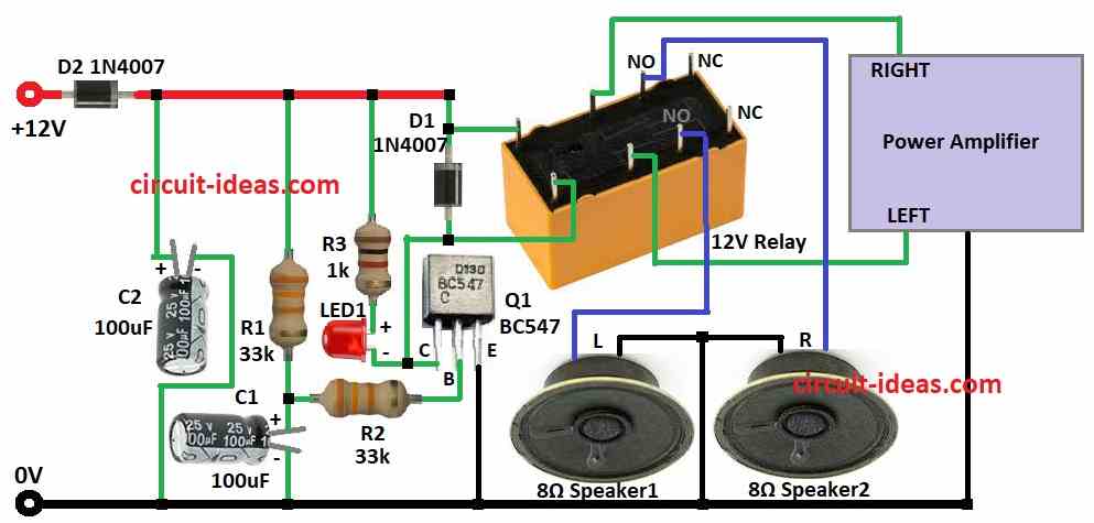
To begin with, we started the circuit with a switch a special type called 12V DC DPDT relay, which controls connection between amplifier and speaker; also, this relay work like normal switch but it uses electricity to turn ON/OFF not hand.
Furthermore, we use 12V relay because it is easy to find, also relay coil has resistance with around 180 ohms; so it need small current to about 0.067 amps to turn ON.
We used 12V power supply which gives at least 300 milliamps to power it, also we need extra part called transistor to turn ON the relay.
Therefore, we use the BC547 NPN transistor because it can supply sufficient current to drive the relay coil, additionally, the circuit diagram illustrates how all the components connect to one another.
Transistor connect in common emitter way and it can work with very weak signal, so we put diode across relay coil for safety which protects transistor from high voltage when relay turns OFF.
We also add LED with resistor to show if transistor and relay work correct.
A capacitor and extra diode help circuit work better and protect from wrong power connection and if there is no DPDT relay then we can use two single relays together; hence, this reduce total resistance and help transistor switch better.
As a result, if circuit does not work, then maybe transistor is bad then try to replace the transistor and if can not replace then try change values of parts, or maybe make C1 capacitor bigger and R2 resistor smaller.
Finally, if 3 second delay is not enough then use bigger C1 to make longer delay.
Formulas:
We use formulas to make speaker turn ON delay circuit with transistor and RC delay.
Time constant (τ) of RC circuit is:
τ = R × C
where:
- R is resistor R1 in ohms
- C is capacitor in farads
Delay time (tdelay) in seconds is:
tdelay = 1.1 × τ
So,
tdelay = 1.1 × R × C
If we want to find R for a set delay time then we can use formula:
R = tdelay / (1.1 × C)
This circuit gives simple delay to help speaker or amplifier turn ON after short time using RC and transistor, so change values of R and C to get delay time as we need.
How to Build:
To build a Amplifier Speaker Turn-On Delay Circuit follow the below mentioned steps:
- First, gather all parts shown in the circuit diagram.
- Next, connect collector of transistor Q1 to +12V through resistor R3 and LED1, connect base of Q1 to resistor R2 and connect emitter of Q1 to ground.
- Then connect resistor R1 and capacitor C1 from +12V to ground and also connect capacitor C2 from +12V to ground.
- Now connect relay coil between collector of Q1 and +12V and then connect relay poles to left and right audio output from amplifier.
- Also, connect relay NO contacts to left and right speakers.
- Finally, connect diode D1 across relay coil terminals and also connect diode D2 to +12V supply.
Safety Tips:
- Be careful as circuits can have dangerous current and voltage, always put safety first when building circuits or ask expert if not sure about any part.
Conclusion:
Overall, this Amplifier Speaker Turn-On Delay Circuit stops speaker from connecting too early and removes “thump” noise when amp starts; also it uses simple easy to find parts, but always stay safe when working with electronics.
Leave a Reply