Imagine we have a strong water hose of 12V, but plant need soft sprinkle with 3.3V to 3.5V, then in that case a Buck Converter Circuit for 1 Watt LED Driver is like adapter for hose.
Also, it makes pressure low and is good for plant and it control water flow like current, so plant do not get too much of water.
Similarly, the circuit keeps the LED bright and prevents it from burning out.
Circuit Working:
Parts List:
| Components | Values | Quantity |
|---|---|---|
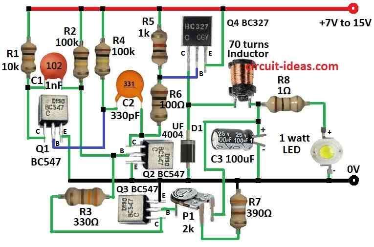
| Resistors | 10k, 330Ω, 1k, 100Ω, 390Ω, 1Ω (1/4 watt ) | 1 each |
| 100k (1/4 watt) | 2 | |
| Preset 2k | 1 | |
| Capacitors | Ceramic 1nF | 1 |
| Ceramic 330pF | 1 | |
| Electrolytic 100μF 25V | 1 | |
| Semiconductors | Transistors BC547 | 3 |
| Transistor BC327 | 1 | |
| Diode UF4004 | 1 | |
| 1W LED | 1 | |
| Inductor 10mH with 70 turns of 0.25mm wire wound around its core | 1 |
This buck converter give power to 1 watt white LED using 12V and constant 300mA current, also it uses BC327 transistor and 10mH inductor with 70 turns of 0.25mm wire.
Here, the LED operates between 3.3V and 3.5V and additionally, resistor R8, with a value of 1Ω, helps measure the LED current.
300mV drop = 300mA current.
Also, use a high-speed diode; otherwise, the current can increase by 50mA.
Therefore, this circuit works well because it prevents current spikes in the LED.
So want more current? then use little lower resistor than of 390 ohm.
Formulas:
When making a buck converter for 1 watt LED we must think about efficiency, frequency and which parts to use, also here are simple formulas to help build the circuit:
Output Voltage (Vout):
Vout = Vin × (D / (1 – D))
where,
- Vin is the input voltage
- D is the duty cycle with switch ON time ÷ total time
Duty Cycle D:
D = Vout / (Vin + Vout)
Inductor Current IL:
IL = Vout × (1 – D) / (L × Ton)
where,
- L is the inductor value
- Ton is the switch ON time
Switching Frequency (f):
f = 1 / T = Vin / (L × (Vin – Vout) × IL)
- T is the total time for switching period
These formulas help us design the circuit, also exact values depend on our LED needs and power input.
How to Build:
To build a Buck Converter Circuit for 1 Watt LED Driver we need to follow the below mentioned steps for connections:
- First, connect Q1 collector to positive supply through R1, connect Q1 base to R4 and C2 and then connect Q1 emitter to ground.
- Next, connect Q2 collector to R5 and R6, connect Q2 base to positive supply through R2 and then connect Q3 emitter to ground.
- Then connect Q3 collector to one side of R3 and other side of R3 goes to Q2 base, connect Q3 base to one leg of P1 preset and then connect Q3 emitter to ground.
- After that, connect Q4 collector to ground through D1 diode, connect Q4 base between R5 and R6 as they are in series and then connect Q4 emitter to positive supply.
- Now connect inductor coil and R8 in series from Q4 collector and also, connect C3 capacitor between inductor and R8 and then connect 1W LED from R8 to ground
- Connect C1 capacitor between R1 and R2.
- Finally, connect R7 resistor from other leg of P1 preset to ground.
Safety Note:
- Use parts that can handle voltage, current and heat and add short circuit protection to avoid damage if LED shorts.
Conclusion:
To conclude, this Buck Converter Circuit for 1 Watt LED Driver lowers high voltage to LED voltage and gives steady current, it also keeps LED safe and by working right.
Leave a Reply