This article for Cellphone Triggered Car Amplifier Auto Mute Circuit show how to make one simple circuit, like when phone ring it turns OFF the car music by itself.
So no need to rush or search button to stop music when call is coming.
What is a Cellphone Triggered Car Amplifier Auto Mute Circuit:
The Cellphone Triggered Car Amplifier Auto Mute Circuit is one small electric setup; where it stops car music when phone ring inside the car.
Furthermore, main idea of this circuit is to help when loud music make hard to hear or answer phone call, also it work by itself with no need to press any button.
Hence, when phone call come it mute car speaker and this makes things easy and better for user.
Circuit Working:
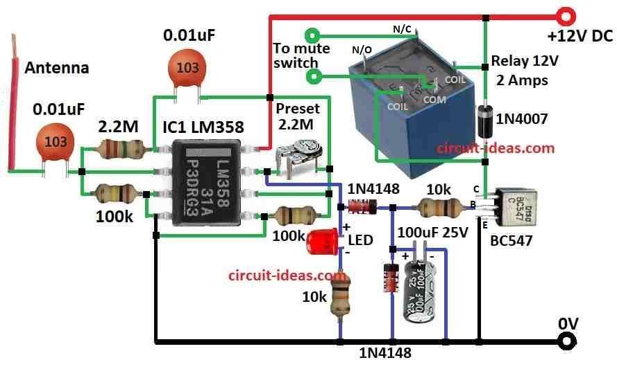
Parts List:
| Components | Values | Quantity |
|---|---|---|
| Resistors (All resistors are 1/4 watt) | 2.2M | 1 |
| 10k | 2 | |
| 100k | 2 | |
| 2.2M | 1 | |
| Capacitors | Ceramic 0.01uF | 2 |
| Electrolytic 100uF 25V | 1 | |
| Semiconductors | IC LM358 | 1 |
| Transistor BC547 | 1 | |
| Diode 1N4148 | 2 | |
| Diode 1N4007 | 1 | |
| LED 5mm 20mA | 1 | |
| Relay 12V 2 Amps | 1 |
Let us see how the above circuit help to do this job; as we know when mobile phone is ON and making or getting call it make some strong radio signal and we call it RF (radio frequency).
Also, all phones give out this RF when calling even if signal strength is not same for all; hence there is always some RF around phone even with rules in place.
As a result, this RF from phone can help us know if phone is working or not and we can use this signal to do switching using circuit.
RF Sniffer Part:
When someone makes or receives a phone call inside the car, this circuit, called an RF sniffer, detects the signal and uses it to mute the music from the car amplifier.
This circuit have two parts:
- One relay driver with BC547 transistor
- And RF sensor using two amplifiers A1 and A2
To detect even weak signals, A1 and A2 work as high-gain amplifiers and connect one after another to increase the signal strength.
Therefore, there is one feedback resistor 2M on IC2 that control how strong the op-amp is; and if we increase this resistance and its sensitivity goes up and if we reduce it the sensitivity goes down.
Also, these op-amps are very good at catching different RF signals in air.
Moreover, we can adjust one 2.2M preset to set how sensitive the circuit is and depending how much RF is in the place.
It is important to set the sensitivity correctly so the circuit only detects RF signals from a phone and does not respond to noise from the car engine or other sources.
We can also place many of these sensor units in different parts of the car and connect their outputs to the main relay driver.
This method allows the circuit to detect the phone signal even when the phone is in the backseat.
At the same time, each sensor stays sensitive enough to detect mobile RF signals without responding to other noise.
How It Works:
So when phone call happen antenna in circuit catches the RF signal and then it turn that into DC signal with more power which is depending how strong phone signal is.
Also, this strong signal goes to relay part which have some diodes and capacitors to clean the signal.
After that, when the relay turns ON, it sends a signal to the mute pin of the car amplifier, which stops the music for some time until the phone call finishes.
Formula:
Here are some formulas for the Cellphone-Triggered Car Amplifier Auto-Mute Circuit.
We can also use the following formula for the inverting amplifier circuit:
Vout = -Iin × R3
where:
- Vout is output voltage from the amplifier
- Iin shows input current going into amplifier
- R3 is resistor in the circuit with certain resistance
How this formula works:
This circuit takes a small current (Iin), increases it and gives it as output voltage (Vout); also, the minus sign (−) in the formula means the output voltage reverses.
So, if the input current is positive, the output voltage becomes negative, which is how an inverting amplifier works.
How to Build:
To build a Cellphone Triggered Car Amplifier Auto Mute Circuit following are the connections steps:
Assemble the Parts:
- First, collect all the parts as we can see in the circuit diagram above.
Circuit Connections:
- Next, put all parts on PCB (printed circuit board) using the diagram as our guide and be careful while fixing IC, diode and transistor and place them correct way.
RF Sensor Stages A1 and A2:
- Then connect two LM358 op-amps one after another for the RF sensor, call them A1 and A2 and connect a 2.2M preset resistor as feedback to control the sensitivity.
Relay Driver with BC547:
- Also, use BC547 transistor to make relay driver stage and connect the relays common pin to the car amplifiers mute terminal and connect relay coil to collector of transistor.
Adjusting Sensitivity:
- After that, to change sensitivity turn the 2.2M preset and this will help remove unwanted RF signals and it only let phone signal trigger the mute.
Adding More RF Sniffers:
- Also, if needed we can add more RF sensor units in different places in the car and connect their output wires to the main relay circuit.
- Give power to the circuit using correct power source and be sure the voltage is safe for all parts.
Test and Adjust:
- Then put circuit inside car and turn it ON and now try calling from a phone, also adjust the sensitivity to ensure circuit catches RF from phone and not from engine or other things.
Final Check:
- Before finishing check all wires again and also be sure there is no loose wire and the mute works every time call happens.
Important Tips:
- Connect the diodes and electrolytic capacitors in the correct direction.
- Check pins of ICs and transistors that they do not mix up and try the circuit first on testing PCB before fixing permanent.
Conclusion:
To conclude, this Cellphone Triggered Car Amplifier Auto Mute Circuit help to stop loud music in car when phone call comes and also it work without touching anything so it makes driving safe and easy.

Leave a Reply