Nowadays, many hobby electronics users like to build interesting sensor projects and an EMF Ghost Detector is one such simple and exciting project.
This EMF Ghost Detector Circuit using Arduino Uno and LCD Display detects electromagnetic field changes around electrical devices, wires and nearby electronic signals.
Also, many people use this type of circuit for science experiments and hobby ghost-hunting activities.
In this project, Arduino Uno reads the EMF signal from an antenna wire through an input pin and then it shows the signal level on the LCD display.
At the same time the LED glows and the buzzer sounds when the EMF level increases and therefore, the user can easily know when the electromagnetic field changes.
This project is easy to build, with low cost and is good for beginners.
Arduino Coding:
#include <Wire.h>
#include <LiquidCrystal_I2C.h>

LiquidCrystal_I2C lcd(0x27, 16, 2);

int emfPin = A0;
int buzzerPin = 8;
int ledPin = 7;
int emfValue = 0;

void setup()
{
pinMode(buzzerPin, OUTPUT);
pinMode(ledPin, OUTPUT);

lcd.init();
lcd.backlight();

lcd.setCursor(0,0);
lcd.print("EMF Detector");
delay(2000);
lcd.clear();
}

void loop()
{
emfValue = analogRead(emfPin);

lcd.setCursor(0,0);
lcd.print("EMF Level: ");
lcd.setCursor(11,0);
lcd.print(emfValue);

if(emfValue > 300)
{
digitalWrite(ledPin, HIGH);
digitalWrite(buzzerPin, HIGH);

lcd.setCursor(0,1);
lcd.print("Field Detected");

}
else
{
digitalWrite(ledPin, LOW);
digitalWrite(buzzerPin, LOW);

lcd.setCursor(0,1);
lcd.print("Normal        ");

}

delay(200);
}
Coding Explanation:
- The above code includes Wire and LiquidCrystal_I2C library and after that it creates the LCD object.
- Next, the code defines the pins A0 for EMF input, D8 for buzzer and D7 for LED.
- In setup section the code starts the LCD and sets buzzer and LED pins as output.
- Then inside loop, Arduino reads analog value from A0 using analogRead().
- After that it shows the EMF value on LCD.
- If the value becomes more than 300 the code turns ON the LED and buzzer which also displays “Field Detected”.
- Otherwise, the code keeps the LED and buzzer OFF and shows “Normal”.
- So this logic gives instant field indication.
Circuit Working:
Parts List:
| Components | Values | Quantity |
|---|---|---|
| Resistor | 470k, 220Ω | 1 each |
| Arduino Uno | Arduino Board | 1 |
| LCD Display | 16×2 with I2C Module | 1 |
| LED | Any Color (Red/Green) | 1 |
| Piezo Buzzer | Piezo Buzzer | 1 |
| Antenna Wire | Single Core Copper Wire / soldering wire | 1 |
In the above circuit, we will make a simple Arduino EMF Ghost Detector with LCD, many believe spirits create energy that disturbs the EMF field and this detector helps sense that change, so lets us understand how its done.
When the antenna wire stays near an electric appliance, mobile phone, Wi-Fi router, AC wiring or any device producing electromagnetic radiation it picks up small voltage fluctuations.
Then Arduino reads this signal at analog pin A0, as the EMF level rises then the analog value increases.
Afterwards, Arduino compares the value with the preset threshold and if the value crosses the limit it activates the buzzer and LED.
Meanwhile, the LCD continuously displays the measured EMF level and as a result, the user gets both visual and sound alert.
For example, when we bring this detector near a charger, monitor or mobile phone during a call the reading usually rises quickly.
How to Build:
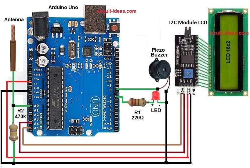
To build a EMF Ghost Detector Circuit using Arduino Uno and LCD Display follow the below connection steps:
Gather all the circuit parts as shown in above diagram:
LCD with I2C connection:
- LCD VCC connect to Arduino 5V
- LCD GND connect to Arduino GND
- LCD SDA connect to Arduino A4
- LCD SCL connect to Arduino A5
Buzzer connection:
- Buzzer positive pin goes to Arduino digital pin 8
- Buzzer negative pin goes to GND
LED connection:
- LED anode connects to Arduino digital pin 7 through 220 ohm resistor
- LED cathode goes to GND
EMF antenna input connection:
- Connect one end of antenna wire to Arduino analog pin A0
- And connect a 470k resistor between A0 and GND
Conclusion:
This EMF Ghost Detector Circuit using Arduino Uno and LCD Display is a simple and interesting Arduino project which helps detect nearby electromagnetic field changes and gives instant alert using LCD, LED and buzzer.
Moreover, beginners can easily build this circuit on breadboard and test it near electrical devices and also the project teaches analog sensing, display interfacing and alarm control in a practical way.
Leave a Reply