LiPo batteries are popular today because they are lightweight, store a large amount of energy and support recharging, however, we must charge them carefully and accurately.
We need a special circuit to prevent overcharging because overcharging can damage a battery or cause a fire.
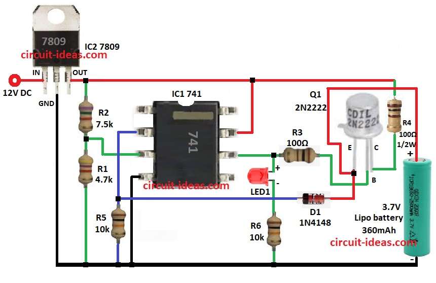
Hence, this LiPo Battery Charger Circuit is simple to build and uses an IC 741 op-amp with a few additional components.
Also the circuit is designed for a 3.7V, 360mAh LiPo battery.
Circuit Working:
Parts List:
| Components | Values | Quantity |
|---|---|---|
| Resistors | 4.7k, 7.5k, 100Ω 1/4 watts | 1 each |
| 100Ω 1/2 watt | 1 | |
| 10k 1/4 watt | 2 | |
| Semiconductors | IC 741 | 1 |
| IC 7809 | 1 | |
| Transistor 2N2222 | 1 | |
| Diode 1N4148 | 1 | |
| LED any 5mm 20mA | 1 | |
| Battery Li-Po Cell 3.7V, 360mAh | 1 |
In this circuit all parts work together to charge LiPo battery, as it takes 12V DC input and IC2 7809 makes it 9V which gives steady power to op-amp IC1 and other parts.
Then IC1 741 op-amp works like comparator and resistors R1 and R2 make a reference voltage at pin 2 of inverting input.
After that, pin 3 non-inverting gets battery feedback through resistor R5 and op-amp output pin 6 controls transistor Q1 using resistor R3.
If battery voltage is low then op-amp turns ON the Q1 transistor and battery starts charging and when battery is full then feedback voltage = reference voltage and op-amp turns OFF the transistor Q1 and charging stops.
Finally, LED1 shows charging status, diode D1 stops reverse current and keeps circuit safe.
Formulas with Calculations:
Below are simple formulas and values for building LiPo battery charger circuit:
1. Reference Voltage (Vref):
Vref = (R2 / (R1 + R2)) × VCC
VCC = 9V, R1 = 4.7kΩ, R2 = 7.2kΩ
Vref = (7.2 / 11.9) × 9 = 5.04V
2. Battery Feedback Voltage (Vfeedback):
Vfeedback = (R5 / (R4 + R5)) × Vbattery
Vbattery = 3.7V, R4 = 100Ω, R5 = 10kΩ
Vfeedback = (10000 / 10100) × 3.7 = 3.66V
3. Charging Current (Icharge):
Icharge = VBE(Q1) / R3
VBE(Q1) = 0.7V, R3 = 100Ω
Icharge = 0.7 / 100 = 7mA
How to Build:
To build a a LiPo Battery Charger Circuit follow below steps for connections:
- First, connect IC2 input pin to 12V DC power, connect IC2 GND pin to circuit GND and then connect IC2 output pin to resistor R2 and then R2 to pin 3 of IC1.
- Next, connect resistors R2 and R5 in series from IC2 output to GND.
- Now, connect pin 2 of IC1 to one end of R5 and other end of R5 goes to GND.
- After that, connect pin 3 of IC1 at the point between R2 and R1.
- Also, connect pin 4 of IC1 to GND.
- Further, connect pin 6 of IC1 to anode of LED1 and cathode of LED1 goes to one end of R6 and other end of R6 to GND and also connect R3 from pin 6 after LED1 and to base of Q1 transistor.
- Then connect emitter of Q1 to positive terminal of 3.7V LiPo battery, connect collector of Q1 to IC2 output through resistor R4 and connect anode of diode D1 to emitter of Q1 and cathode to point between pin 2 of IC1 and R5.
- Finally, connect GND of circuit to negative terminal of 3.7V LiPo battery.
Conclusion:
To conclude, this How to Build a LiPo Battery Charger Circuit is easy, cheap and safe for 3.7V batteries, also it uses IC 741 to control voltage and 7809 to give steady power.
We can add more safety like overcurrent protection or auto shutoff, therefore, with circuit diagram and calculations anyone hobbyist or engineer can build this charger.
Leave a Reply