This project uses a very old LM386 audio amplifier IC and is still one of the best beginner audio amplifier ICs for learning and DIY circuits, which increases the strength of weak audio signals with very few components, it provides enough output power to drive a small 4Ω or 8Ω speaker directly and because of this qualities, many beginners use this IC for small speaker amplifier circuits.
In simple words, the IC takes a low sound signal from a microphone, mobile phone, radio or music player and makes it louder.
In this post, we have two circuit first circuit gives bass boost, so it improves the low frequency sound and makes the audio output deeper and stronger and on the other hand, the second circuit works as a mini audio amplifier, which we can use for small speakers, radios and portable sound projects.
Moreover, both circuits work with low DC voltage, so we can easily run them from a battery or DC supply.
Thus, LM386 Amplifier Circuit with Bass Boost and Mini Audio Amplifier is is easy, cheap and reliable project to build.
Circuit Working for LM386 Amplifier with Bass Boost:
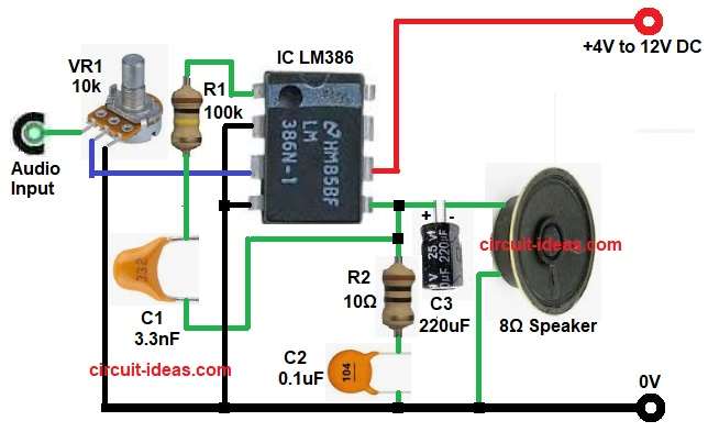
Parts List for Bass Boost circuit:
| Components | Values | Quantity |
|---|---|---|
| Resistors | 10Ω, 100k 1/4 watts | 1 each |
| Potentiometer 10k | 1 | |
| Capacitors | Electrolytic 220uF 25V | 1 |
| Ceramic 3.3nF, 0.1uF | 1 each | |
| Semiconductors | LM386 Audio Amplifier IC | 1 |
| Speaker 8Ω | 1 | |
| Power Supply +4V to +12V DC | 1 |
The IC LM386 itself has a default base gain of 20× which in decibels gives about 26 dB maximum midband gain.
At first, the LM386 amplifier with bass boost takes the weak audio signal from the input source and sends it through the VR1 potentiometer which controls the volume level.
Next, the adjusted signal goes to pin 3 of the LM386 IC where the IC amplifies the audio signal.
Then the amplified output comes from pin 5 and passes through the C3 electrolytic capacitor to the 8-ohm speaker and this capacitor blocks the DC voltage allowing only the audio signal to reach the speaker.
However, in the circuit the R1 and C1 network connected between pin 1 and pin 5 changes the gain according to frequency and this means the gain is not same at every frequency.
Also, the R2 resistor and C2 capacitor at the output side improve the circuit stability and reduce unwanted noise or oscillation.
As a result, the circuit gives louder audio output with enhanced bass response and the circuit gain depends on frequency.
How to Build:
To build a LM386 Amplifier with Bass Boost Circuit follow the below connection steps:
- Start, by collecting all the circuit parts as in diagram above.
- Next, start with IC LM386 with pin 1 connect resistor R1 and capacitor C1 to pin 5 of IC.
- Pin 2 connect to ground.
- Pin 3 connect audio input signal through volume VR1 center pin, upper pin of VR1 goes to audio input and lower pin goes to ground.
- Pin 4 also connect directly to ground.
- Pin 5 is output pin and connect one end of speaker through C3 capacitor and other end of speaker goes to ground.
- From pin 5 connect resistor R2 and capacitor C2 in series and ground.
- Finally, pin 6 connect to positive supply voltage of +4V to +12V.
Circuit Working for Mini LM386 Audio Amplifier:
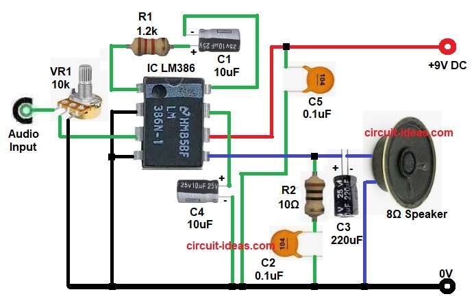
Parts List for Mini LM386 Audio Amplifier:
| Components | Values | Quantity |
|---|---|---|
| Resistors | 10Ω, 1.2k 1/4 watts | 1 each |
| Potentiometer 10k | 1 | |
| Capacitors | Ceramic 0.1uF | 2 |
| Electrolytic 10uF 25V | 2 | |
| Electrolytic 220uF 25V | 1 | |
| Semiconductors | LM386 Audio Amplifier IC | 1 |
| Speaker 8Ω | 1 | |
| Power Supply +9V DC or Battery | 1 |
This circuit works with 9V DC power supply or battery as the circuit input signal first comes through VR1 and then goes to pin 3.
Next, the LM386 amplifies the signal and sends output through pin 5 and then, capacitor C3 couples the signal to the speaker.
Also, resistor R2 and capacitor C2 again work as output stabilization network and capacitor C1 and C4 help improve gain and frequency response.
Therefore, this circuit gives clear and loud sound output in a simple compact design.
How to Build:
To build a Mini LM386 Audio Amplifier follow the below connection steps:
- Start, to collect all the parts as in circuit diagram.
- Then start, with IC LM386 and connect pin 1 and pin 8 through resistor R1 and capacitor C1.
- Next, connect pin 4 and pin 2 to ground.
- Then connect pin 3 of IC to center pin of VR1, VR1 upper pin goes to audio input and lower pin goes to GND.
- Next, connect output capacitor from pin 5 to speaker positive terminal through capacitor C3.
- Connect resistor R2 and capacitor C2 in series from pin 5 and ground.
- Connect pin 7 of IC to ground through capacitor C4.
- Connect pin 6 of IC to positive supply of +9V DC or battery.
- Finally, connect capacitor C5 from positive supply of +9V to ground.
Conclusion:
To conclude, both LM386 circuits give simple and effective audio amplification.
The first circuit gives better bass response, so it works well for music sound projects.
The second mini amplifier circuit gives simple and compact audio output for small speaker applications.
Therefore, if we need deeper sound then choose bass boost circuit and if we need a compact amplifier then use the mini LM386 circuit.
Overall, LM386 Amplifier Circuit with Bass Boost and Mini Audio Amplifier is easy to build, low cost and very useful for beginners and DIY electronics projects.
Leave a Reply