Do anyone like lamps that change color with magic?
This project for RGB LED Color Control Circuit with LDR and Arduino makes its real.
Using RGB LED and three LDR light sensors, we can create a smart lamp that mix colors based on light around it.
Just a simple circuit and with some code, we can get endless color fun.
This circuit is perfect for beginners and hobby makers.
Circuit Coding:
int redPin = 9;
int greenPin = 10;
int bluePin = 11;
int ldrR = A0;
int ldrG = A1;
int ldrB = A2;

void setup() {
pinMode(redPin, OUTPUT);
pinMode(greenPin, OUTPUT);
pinMode(bluePin, OUTPUT);
}

void loop() {
int valR = analogRead(ldrR);
int valG = analogRead(ldrG);
int valB = analogRead(ldrB);

int pwmR = map(valR, 0, 1023, 0, 255);
int pwmG = map(valG, 0, 1023, 0, 255);
int pwmB = map(valB, 0, 1023, 0, 255);

analogWrite(redPin, pwmR);
analogWrite(greenPin, pwmG);
analogWrite(bluePin, pwmB);

delay(50);
}
Coding Explanation:
- Red, green, blue pins set as output.
- It reads analog from three LDR.
- Map analog value to PWM range 0 to 255.
- Write PWM to RGB LED pins.
- LED glow as per light falling on LDR.
- Color mix automatically.
Circuit Working:
Parts List:
| Component | Quantity |
|---|---|
| Resistors | |
| 220Ω 1/4 watt | 3 |
| 1k 1/4 watt | 3 |
| Semiconductors | |
| Arduino UNO | 1 |
| LDR | 3 |
| RGB LED (Red, Green and Blue) | 1 |
This is simple Arduino color mixing lamp circuit.
It can make room corner look nice
Lamp change color when light change in room.
It work automatic and switch color by light condition.
LDR resistance is low when light fall.
LDR resistance is high when its dark.
Arduino read voltage at analog pins A0, A1 and A2.
Arduino change PWM output at pins 9 ,10 and 11.
PWM control LED brightness.
Red, Green, Blue brightness mix to make different colors.
So color of lamp change with light on LDR.
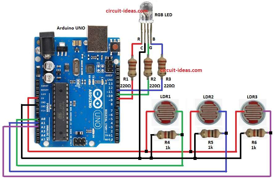
How to Build:
To build a RGB LED Color Control Circuit with LDR and Arduino follow the below steps for connections:
- Arduino pin 9 connect to Red pin of RGB LED through resistor R1.
- Arduino pin 10 connect to Green pin of RGB LED through R2.
- Arduino pin 11 connect to Blue pin of RGB LED through R3.
- Common cathode RGB LED ground pin go to Arduino GND.
- LDR1 connect with resistor R4 and pin A0 of Arduino
- LDR2 connect with resistor R5 and pin A1 of Arduino
- LDR3 connect with resistor R6 and pin A2 of Arduino
- All LDR other side go to 5V.
- Resistors go to ground.
Conclusion:
This RGB LED Color Control Circuit with LDR and Arduino is very simple and very fun project.
RGB LED change color with light sensor.
It is good to learn Arduino, PWM, LDR and RGB mix.
We can use this circuit for smart lamp or room decoration.
Leave a Reply