12 Volt Dual Power Supply Circuit works like two battery in one.
It give two output one is +12V and the other one is -12V and both use same ground.
This circuit is very helpful for electronics project like audio amplifier where we need both plus and minus voltage for good sound.
It is like all power come in small easy circuit.
Circuit Working:
Parts List:
| Category | Component | Quantity |
|---|---|---|
| Capacitors | Ceramic 0.1µF | 2 |
| Electrolytic 1000µF 25V | 2 | |
| Semiconductors | IC 7812 | 1 |
| IC 7912 | 1 | |
| Bridge Rectifier diodes 1N5402 | 4 | |
| Transformer 14-0-14V/1Amp | 1 |
This is normal power supply using both positive and negative voltage IC.
It give +12V and -12V with same ground and is good for amplifier or other project needing equal power both sides.
It can give 1 amp current.
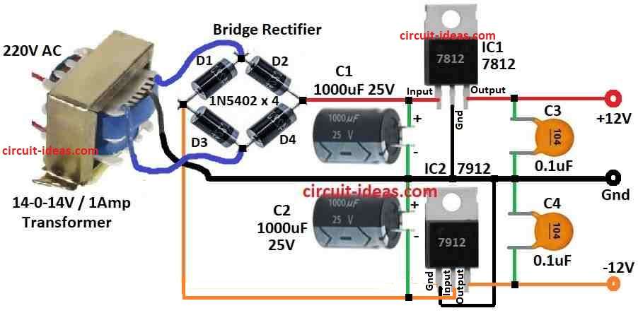
To do this we need to use 14-0-14V, 1 amp transformer which changes 230V AC to around 14V AC.
Then bridge rectifier using 4 diodes 1N5402 D1 to D4 changes AC to DC.
Capacitors C1 and C2 remove ripple from low voltage AC.
Two voltage regulator ICs are used to make +12V and -12V.
IC1 is 7812 it gives +12V.
IC2 is 7912 it give -12V.
But IC2 pin is not the same as IC1 so check circuit diagram before connecting it.
Output come from pin 3 of both ICs we can use this to power our circuit.
Capacitors C3 and C4 helps to remove noise so that DC output is clean.
Formula:
How to find filter capacitor value for 12V dual power supply.
We can use this formula:
C = I / (2 × f × Vpp)
where:
- C is capacitor size in farad
- I is current load in ampere
- f is input frequency in hertz like 50Hz or 60Hz
- Vpp is ripple voltage from peak to peak in volt
Note:
Use bigger capacitor and than we calculate this by giving better filtering.
If we want very clean voltage which is less ripple then we can also add more filter or use voltage regulator IC.
We can calculate and pick correct value of capacitor using above rule.
How to Build:
To build a 12 Volt Dual Power Supply Circuit follow the below mentioned steps.
Things we need (Components):
- One 14-0-14V, 1 amp step-down transformer
- Four 1N5402 diodes for full wave bridge rectifier
- Two voltage ICs: 7812 for +12V, 7912 for -12V
- Capacitors: C1, C2, C3, C4 check circuit diagram for correct values
- Other small things: wires, soldering iron, PCB board etc.
How to Make the Circuit:
- Connect 230V AC power to the input side primary of transformer.
- Connect output side secondary of transformer to diode bridge full wave rectifier.
- Connect output from rectifier to capacitors C1 and C2 and be careful with + and – sides.
- Connect output from capacitors to input pins of voltage ICs.
- Connect output pin 3 from ICs to capacitors C3 and C4 and again check polarity (+/-).
Check Everything:
- Look at the diagram and check all wire connections.
- Be sure all parts are soldered good and placed correct.
- Use multimeter to check output voltage at ICs pin 3.
- We should see +12V from 7812 and -12V from 7912.
- Voltage must be stable.
Adjust If Needed:
- If voltage is not right change parts or check the connections.
Box It Up:
Final Check:
- Do last test to be sure circuit gives correct voltage and works well.
Be Careful:
- This project use high voltage 230V so be very careful.
- If anyone do not know much about electronics then ask someone who knows or get help from expert.
Conclusion:
12 Volt Dual Power Supply Circuit gives two output one +12V and one -12V and both are connected with same ground.
It is mostly used in electronics project where we need same power on both side like audio amplifier.
Leave a Reply