Air Flow Detection Circuit means basic electric circuit to check if air is moving or not; also people use this in machines or home projects to watch air flow.
Furthermore, in this project we make very simple circuit to see if air is moving and also we used broken AC bulb and few cheap parts to feel air.
Therefore, this is fun and easy project with parts we can find easily.
Circuit Working:
Parts List:
| Components | Values | Quantity |
|---|---|---|
| Resistors (All resistors are 1/4 watt unless specified) | 100Ω | 1 |
| 680Ω | 1 | |
| 330Ω | 1 | |
| 10k | 1 | |
| Preset 50k | 1 | |
| Capacitors | Electrolytic 100μF 25V | 1 |
| Semiconductors | IC LM358 | 1 |
| IC 7805 | 1 | |
| LED yellow 5mm 20mA | 1 | |
| Broken filament bulb | 1 | |
| DC fan | 1 | |
| Push button | 1 |
This circuit uses small broken filament bulb to feel air moving as filament are special so when it gets hot the resistance goes down not like normal.
When power is ON and there is no air then filament gets little hot and resistance gets low and if air blows, filament cools like mini fan and resistance goes high; hence, circuit sees this change like secret signal.
Also, op-amp IC1 LM358 reads this signal and changes it to simple output and op-amp works like judge and it checks if air is more than set level.
If air movement reaches the set level, LED1 turns ON like an indicator light and shows that air is moving and we can adjust the amount of air needed to turn on the LED by using preset VR1.
Moreover, 12V battery gives power and also there is push button and small fan to test airflow and we can also blow on filament to see LED1 lights up.
Formulas:
Here, is simple way to explain how to design air flow detector circuit:
Finding Threshold Voltage (Vth):
We use preset (P) to set voltage at non-inverting pin of LM358 and if total resistance is P ohms and bottom resistor is R ohms then the formula is:
Vth = P / (P + R) * Vcc
where:
- P is the preset resistance
- R is the resistance to ground
- Vcc is the power supply voltage
As a result, this formula gives basic idea to build air flow circuit and we may need to change values based on our project or environment.
How to Build:
To build a Air Flow Detection Circuit we need to follow the below mentioned steps:
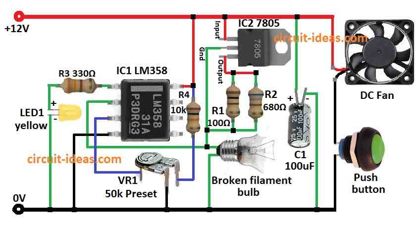
IC1 Connection:
- First, put all parts same like shown in circuit diagram.
- Next, connect pin 1 of IC1 LM358 to ground through resistor R3 and LED1.
- After that, connect pin 2 of IC1 to one side of broken bulb and other side of bulb to ground.
- Then connect pin 3 of IC1 to first leg of VR1 preset, second leg of VR1 goes to positive supply through resistor R4 and then third leg goes to ground.
- Also, connect pin 4 of IC1 to ground and then connect pin 8 of IC1 to positive power.
IC2 Connection:
- Now connect input pin of IC2 7805 to positive side of DC fan and other fan wire to ground through push button, connect ground pin of IC2 7805 to pin 2 of IC1 and then connect output pin of IC2 7805 through resistors R1 and R2 to pin 2 of IC1.
- Also, connect capacitor C1 from IC2 input pin to ground.
Safety Tips:
- Use low voltage power for testing first and if anyone smells something strange or see smoke then stop, maybe a part is bad.
- If anyone is not sure how to build circuits then ask someone with electronics knowledge and be careful as safety is most important.
Conclusion:
Overall, this Air Flow Detection Circuit shows airflow using a broken bulb that changes with temperature; also when air blows the bulb resistance changes and LED turns ON.
Hence, it is a smart and easy using cheap parts and always stay safe when building or testing.
Leave a Reply