EMFs (electromagnetic fields) are invisible energy from electricity and lights which are natural and man made.
Some EMFs are safe and some are bad if used too much for long time.
We can use simple Arduino tool to find EMFs around us.
Moving electric charge make EMFs.
EMFs have two parts: electric field and magnetic field and they move like waves.
Wires and technology devices make EMFs.
Some people worry EMFs can harm health if exposed too much.
We can find EMFs using Faradays Law.
Law says changing magnetic field makes voltage in wire.
We check voltage to know how strong EMF is.
Arduino can read this voltage.
Arduino can change voltage to numbers.
We can show result on LED, LCD, 7-segment or graph on computer by using processing software.
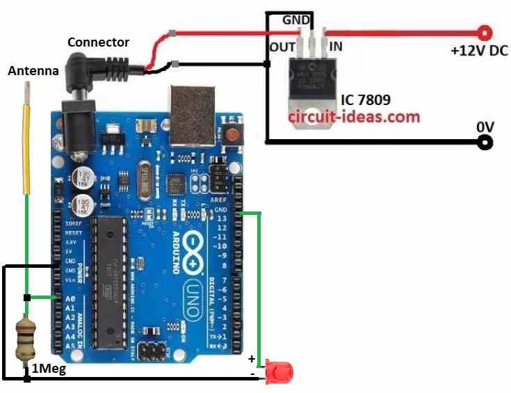
To make this Simple Arduino Based Electromagnetic Field Detector Circuit we used Arduino UNO, 1M resistor, IC 7809 voltage regulator and one spiral wire as antenna.
Code:
const int sensorPin = A0;  // Pin connected to the 1MΩ resistor
const int ledPin = 13;      // Pin for the LED (optional)
int sensorValue = 0;        // Variable to store sensor value

void setup() {
  Serial.begin(9600);       // Initialize serial communication
  pinMode(ledPin, OUTPUT);  // Set the LED pin as an output
}

void loop() {
  sensorValue = analogRead(sensorPin); // Read the voltage from the antenna
  Serial.println(sensorValue);          // Print the sensor value to the Serial Monitor

  // Basic threshold for LED indication
  if (sensorValue > 100) {
    digitalWrite(ledPin, HIGH); // Turn on LED if EMF is detected
  } else {
    digitalWrite(ledPin, LOW);  // Turn off LED if no EMF
  }

  delay(100); // Short delay for readability
}
Code Explanation:
- Sensor connect to analog pin A0.
- LED connects to digital pin 13.
- Code starts serial communication at 9600 baud to see data on Serial Monitor.
- In loop Arduino keep reading antenna value from analog pin.
- This value shows on Serial Monitor.
- If value goes above set limit like100 then LED turns ON to show EMF is there.
Circuit Working:
Parts List:
| Component | Quantity |
|---|---|
| Resistor | |
| 1M 1/4 watt | 1 |
| Semiconductors | |
| Arduino UNO board | 1 |
| IC 7809 | 1 |
| Red LED 5mm 20mA | 1 |
| Wire as antenna | 1 |
Spiral wire works like antenna and picks EMF signals from around.
It take normal wire and coils it.
One end goes to ground and other end connects to one side of 1M resistor.
Other side of resistor goes to analog pin like A0.
1M resistor makes signal weaker and stays safe for Arduino to read.
Analog pin gets voltage from antenna.
Arduino changes it to digital number.
LED shows simple EMF signal but Serial Monitor shows real time EMF changes.
How to Build:
To build a Simple Arduino Based Electromagnetic Field Detector Circuit following are the steps to follow for connections:
- Take all parts as shown in circuit diagram.
- Use IC 7809 to give stable 9V DC power to Arduino.
- Connect one end of spiral wire antenna to one side of 1M resistor.
- Other end of wire goes to ground.
- Connect other side of resistor to analog pin A0 on Arduino.
- If we want LED signal then connect LED with resistor to digital pin D13.
Conclusion:
This Simple Arduino Based Electromagnetic Field Detector Circuit is good for beginners and curious people.
Easy parts like IC 7809, resistor and spiral wire can make working EMF detector.
It is good for learning Arduino and basic electronics.
We can upgrade with data logging or better sensors to make it stronger EMF monitor.
Leave a Reply