Automatic Staircase Light Circuit turn ON light when someone uses stairs and after some time it turn OFF by itself automatically; also it help keep home safe and saves electricity.
Circuit Introduction:
Regular stair lights:
We turn the system ON and OFF manually using switches at the top and bottom; however, sometimes people forget to switch it OFF, which leads to energy wastage.
Automatic stair lights:
Use motion sensor to see if someone is on stairs and light turns ON when it sees person and then turns OFF after some time to save energy.
How it works:
Motion sensor feel body heat like special detector and when it sense person it send signal to turn ON the light; also sensor is easy to use and can change how sensitive it is and how long light stays ON.
Circuit Working:
Parts List:
| Components | Values | Quantity |
|---|---|---|
| Resistor | 1k 1/4 watt | 1 |
| Capacitors | Electrolytic 100μF 25V | 1 |
| Electrolytic 10μF 25V | 1 | |
| Semiconductors | IC LM7805 | 1 |
| IC2 PIR Sensor | 1 | |
| Transistor BC547 | 1 | |
| Diode 1N4007 | 1 | |
| Relay 5V | 1 | |
| 220V to 120V Bulb | 1 |
This circuit is simple because it uses common and easy to find parts.
PIR sensor has two main connections one for output signal and one for sensitivity control; the output goes to transistor Q1 through resistor R1.
Furthermore, relay SPDT type is special switch and it gets power from Vcc and works like a normal switch.
When transistor Q1 turns ON relay coil gets power and light turns ON and when transistor is OFF relay stays open so light stays OFF.
So to give steady power we used bridge rectifier, which change AC from home to pulsing DC.
Then IC 7805 makes it smooth 5V DC and this is good for PIR sensor and other small parts.
We connect the bulb to the phase line and the relays N/O contact and we connect the relay pole to the AC neutral line.
Moreover, we have also use a step-down transformer that converts 230V AC to 9V AC at 500mA.
Finally, PIR sensor needs time to settle and for 10 to 50 seconds after power ON it gives random signals before working properly.
Formulas:
We can make easy circuit with PIR sensor to turn stair light ON when it sees motion and OFF after some time.
Important Formula:
To find base resistor RB for BC547 transistor:
RB = Vin−VBE / IB
where:
- Vin is the voltage from PIR sensor
- VBE is the base-emitter voltage which is about 0.7V for BC547
- IB is the base current
Above formulas helps us to ensure transistor works properly and turns ON fully.
Using PIR sensor and relay this circuit is simple way to control stair light and light turns ON when person comes and turns OFF after delay.
Hence, we can change things in circuit depending on how we want it to work.
How to Build:
To build a Automatic Staircase Light Circuit follow the below mentioned steps:
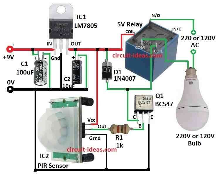
- First, gather parts as shown in diagram.
- Next, connect IN pin of IC1 7805 to 9V power supply, connect GND pin of IC1 to ground and connect OUT pin of IC1 to first leg of 5V relay.
- Then, place capacitor C1 between IN pin of IC1 and ground and also place capacitor C2 between OUT pin of IC1 and ground.
- After that, connect diode D1 from OUT pin of IC1 to third leg of relay.
- Now connect Vcc pin of PIR sensor IC2 to OUT pin of IC1 5V, connect OUT pin of PIR sensor to base of transistor Q1 through resistor R1 and then connect GND pin of PIR sensor to ground.
- Also, connect collector of Q1 between diode D1 and relay, connect base of Q1 to PIR OUT and emitter of Q1 to ground.
- Lastly, connect bulb 220V or 120V between center leg and fourth leg of relay.
Safety Notes:
- Check all smoke detectors in our home especially near stairs and install emergency lights for power cut situations; also keep a backup battery light handy.
Conclusion:
To conclude, this Automatic Staircase Light Circuit uses a PIR sensor to turn ON light when it detects motion, it helps save energy and works with common parts.
Also, we can adjust sensitivity and timing too and always follow safe wiring practices and if not sure ask for help from a licensed electrician.
Leave a Reply