This Battery Charger Circuit using IC TP5000 charges lithium and LiFePO4 battery, also it uses TP5000 IC and this IC work as buck converter and gives fast charge with no over heat.
Furthermore, circuit is small, simple and safe for battery.
Circuit Working:
Parts List:
| Components | Values | Quantity |
|---|---|---|
| Resistors | 1k 1/4 watt | 1 |
| 0Ω 1/4 watt | 1 | |
| 0.1Ω 1/4 watt | 1 | |
| Capacitors | Electrolytic 10μF 25V | 3 |
| Ceramic 100nF | 1 | |
| Semiconductors | IC TP5000 | 1 |
| Inductor 47μH | 1 | |
| Diode SS34 | 1 | |
| LEDs Red and Green 5mm 20mA | 1 each | |
| Li-ion Battery 3.7V | 1 |
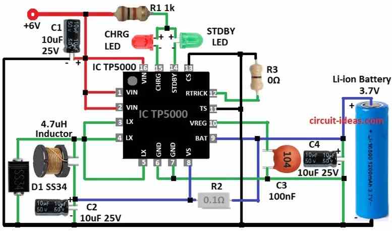
To begin with, this circuit use TP5000 battery charge IC, as it work like buck converter so it can handle more current and does not heat much.
Here, VIN pin 1,2,16 connect input voltage 4.5V to 9V and LX pin 3,4,5 connect to inductor output and give charge current.
Then BAT pin 9 connects to positive battery terminal and then VREG pin 10 is a internal power supply.
After that, TS pin 11 checks battery temperature and then RTRICK 12 pin set constant current with resistor.
Further CS 13 pin set LiFePO4 3.6V mode and then STDBY 14 pin is low signal when charge is complete.
Also, pin CHRG 15 show charge status with pins 14 and 15 connected LED.
By default module is Li-ion charger then remove solder jumper F to use for LiFePO4.
0Ω jumper set pre-charge current with 10% battery current and 0.1Ω resistor set charge current with 1A.
If required, add one more 0.1Ω resistor parallel to charge current to 2A if need heatsink and then replace 0Ω jumper with 50k resistor to increase pre-charge current.
Formulas:
TP5000 Battery Charger Formulas:
1. Charging Current:
Icharge = (Vin – Vbat) / R
where,
- Vin is 6V
- Vbat is 3.7V
- R is R2
2. Capacitor Value (for ripple):
C = (I × t) / ΔV
where,
- I is the charge current,
- t is the discharge time for second
- ΔV is the allowed ripple voltage
How to Build:
To build a Battery Charger Circuit using IC TP5000 follow the below steps for connections:
- First, take all parts same like is circuit diagram.
- Next, pin 1, 2, 16 go to +6V.
- Then pins 3, 4, 5 join together and pin 4 go to 4.7µH inductor and other side to positive of C2.
- After that, D1 cathode join pins 3, 4, 5 and inductor.
- Now pin 6 go to C4 10µF and C3 100nF capacitors and then pin 7 join pin 6.
- Also, R2 0.1Ω connect between pins 8 and 9 and then pin 9 go to positive of 3.7V battery and negative go to GND.
- Further, C3 100nF connect between pin 10 and GND and then C4 positive side goes to pin 9 and negative side go to GND.
- Now pins 11 and pin 13 go to GND and also pin 12 go to 0Ω resistor then GND.
- Green LED cathode goes to pin 14 and red LED cathode pin goes to pin15 and both anodes go to +6V with R1 1k resistor.
- Finally, C1 10µF positive side go to +6V and negative go to GND.
Conclusion:
To conclude, Battery Charger Circuit using IC TP5000 good for lithium and LiFePO4 battery, as it uses buck converter, strong and no overheat in high current.
Also, it have features like temperature check, current control and charge setup and user can change resistor and jumper for battery need.
Therefore, circuit is good choice for home or work, simple and for safe charging.
Leave a Reply