Digital Dice Circuit is small electronic like thing, which work like real dice and shows number from 1 to 6; it also uses lights and buttons which is no need to throw.
As a result, this circuit is good for games and fun and is easy to build.
Circuit Working:
Parts List:
| Components | Values | Quantity |
|---|---|---|
| Resistors (All resistors are 1/4 watt) | 1k | 2 |
| 100k | 1 | |
| Potentiometer 10k | 1 | |
| Capacitors | Electrolytic 10μF 25V | 1 |
| Semiconductors | IC 555 | 1 |
| IC 4017 | 1 | |
| LEDs 5mm 20mA | 6 | |
| Push button | 1 | |
| 9V Battery | 1 |
When playing games like snake and ladder the normal dice can get bad or unfair after long time; but this digital dice is better and more fair, as it uses electric parts but with no cheating.
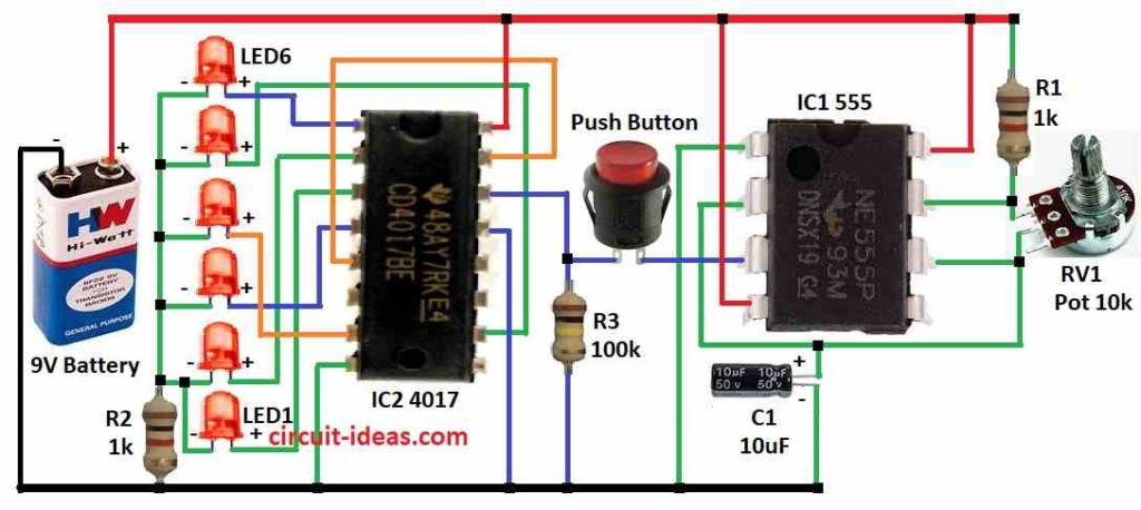
Here, in this circuit main parts are 4017 and 555 timer IC and there are 6 LEDs with each from number 1 to 6.
Press the button to make the LEDs blink rapidly one by one and also release the button to stop the blinking and select a number.
The LED that remains ON indicates the rolled number, for example, if LED 5 remains ON, the rolled number is 5.
Then 4017 IC checks which LED is ON and 555 timer controls how fast LEDs blink.
Also, a part called potentiometer RV1 can change the speed of blinking., where more speed means faster LED blinking.
Finally, there is a formula to find frequency of 555 timer and we keep frequency which is very high so no cheating; also we can turn potentiometer to change this speed.
Formulas:
The digital dice uses 555 IC in astable mode to make timing pulses, also the below formula helps find how fast it works:
F = 1.44 / (R1 + 2 × RV1) × C1
where:
- F is the frequency and how fast LEDs blink
- R1 fixed resistor
- RV1 is variable resistor that is potentiometer which we can turn
- C1 is capacitor and it gives the timing with the resistance.
- R1 + 2 × RV1 means total resistance.
This formula shows how 555 IC makes square wave signals and by changing R1, RV1 or C1 changes the speed of LED blinking.
Furthermore, this is important to control how the digital dice works.
How to Build:
To build a Digital Dice Circuit we need to follow the below mentioned components connections process:
IC 555 Connections:
- First, pin 1 connects to ground.
- Next, pin 2 connect to pin 6
- After that, pin 3 connects one leg of push button
- Then pin 4 connects to 9V positive and also pin 8 connects to 9V positive
- Now pin 6 connects to one leg of 10k potentiometer and pin 7 connects to other leg of 10k potentiometer
- Also, pin 2 connects to one side of capacitor C1 and other side of C1 and ground
- Lastly, R1 connects between 9V positive and pin 7
IC 4017 Connections:
- First, pin 1 connects to LED 6 anode
- Next, pin 2 connects to LED 2 anode
- After that, pin 3 connects to LED 1 anode
- Then pin 4 connects to LED 3 anode
- Now pin 5 connects to pin 15
- Then pin 7 connects to LED 4 anode
- Also, pin 8 and pin 13 connects to ground line.
- Pin 10 connects to LED 5 anode
- Next, pin 14 connects to push button and lastly, pin 16 connects to 9V positive
LED Cathodes:
- LED 2, 3, 4, 5, 6 cathodes connects to ground through R2 and LED 1 cathode join with LED 2 cathode
Safety Tips:
- Handle parts carefully and use correct tools
- Check all wires before turning on the equipment and if anyone is having any doubts, ask an expert for help or write in comment box.
Conclusion:
Overall, Digital Dice Circuit give random number like real dice, as it is fun and fair.
Moreover, build our own with simple parts and show the skills and also be safe and enjoy learning electronics!
Leave a Reply