Simple Earth Fault Indicator Circuit is like safety guard for electric system, as it checks if electric connects to ground by mistake, like when bad wire touch metal box.
Also, this is very important because if there is an electric leak the machine may break and cause a fire or may shock people.
Circuit watch how much electric goes in ground wire, but normal time not much electric current goes there may be nothing.
But if something is wrong more electric go in ground wire; then circuit see this and make alarm sound like light or buzzer to say problem has happen.
Circuit Working:
Parts List:
| Components | Quantity |
|---|---|
| Resistors | |
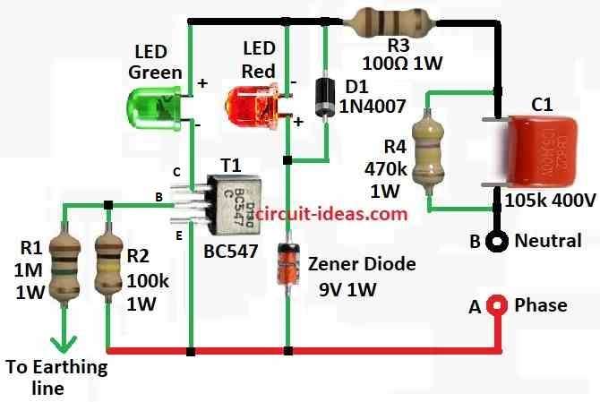
| 1M 1/4 watt, 100k 1 watt, 100Ω 1 watt, 470k 1 watt | 1 each |
| Capacitors | |
| PPC 105k 400V | 1 |
| Semiconductors | |
| Transistor BC547 | 1 |
| Zener diode 9V 1 watt | 1 |
| Diode 1N4007 | 1 |
| Green 5mm 20mA, Red 5mm 20mA | 1 each |
To begin with, change the design and settings if needed depending on the use, because this circuit connects directly to mains power and checks whether the wiring is okay or not.
Also, in home wires good earth wire is very important, because if metal part of machine touch live wire by mistake earth help send electric to ground safe way.
This circuit has LED lights to show wire status:
- Red + Green both ON all wires (phase, neutral, earth) are okay.
- Both OFF maybe power cut or phase/neutral wire broken.
- Red ON only: Phase and neutral okay but earth wire maybe broken.
- Green OFF shows the earth wire is not connected or has a problem.
Circuit take power using parts C1 and R3, as C1 capacitor drop high AC voltage to small safe level and R3 resistor stops too much current coming in fast.
Moreover, R4 help empty out power in C1 when the circuit is unplug.
Zener diode keep voltage safe so transistor T1 does not get damage and this Zener diode make voltage like square wave which depend on Zener value as in this circuit it is 9V.
When 230V is between phase and neutral then transistor T1 turn ON in negative AC half cycle
Then green LED lights up and show earth wire is good and this happen because T1 base get voltage from phase to earth.
Hence, if the earth wire breaks, no voltage reaches the base, so T1 stays OFF and the green LED does not light up.
Red LED will turn ON in positive AC half cycle by showing that phase and neutral are working fine.
To use this circuit:
Put all parts inside 3 pin plug and follow the below connection:
- Point A to Phase pin
- Point B to Neutral pin
- Point C to Earth pin
Then plug in the socket which will show if wiring is correct or not.
Formula:
When current in live and neutral wires are not same that mean some electric current maybe is going to ground (earth).
Earth Fault Indicator Circuit can find this problem.
Below is a simple idea for building this type of circuit and the section also gives some useful formulas.
We use two resistors to make smaller voltage and this small voltage can go to transistor base or for set reference voltage.
Formula:
Vout = Vin × R2 / R1 + R2
- We can change R1 and R2 to get the voltage one wants.
Transistor Bias:
To turn ON transistor we need to send current to base this is base current (IB).
Formula:
IB = Vin−VBE / RB
where,
- RB is resistor at base
- VBE is around 0.7V voltage drop from base to emitter.
To protect LED from too much current we have used resistor.
How to Build:
To build a Simple Earth Fault Indicator Circuit follow the below mentioned steps for connection:
- First, before starting learn safety rules for working with high voltage, wear gloves, shoes and use safe tools.
- After that, look at the circuit diagram carefully and try to understand what each part do.
- Also, take all parts one need as shown in the diagram and check values and type.
- If using PCB solder all parts on board same as diagram and if using breadboard put parts in right place and connect with jumper wires.
- After building and testing put circuit in safe box.
- Before give power check all wires and parts one more time and use multimeter to see if there are any short circuit or wrong connection.
- When all looks good plug into socket and check LED lights and they will show if wiring is okay or not.
- After testing remove from socket and then check again and be sure there are no loose wires or parts moving.
- If one is not sure how to build or test the circuit ask someone with experience or professional person to help.
Conclusion:
To conclude, Simple Earth Fault Indicator Circuit is very important part in electric system, as it finds earth fault early and gives the warning.
Also, this help stop electric shock, fire or damage to machines, it also checks how much current goes in earth wire.
Hence, this help keep place safe at home or factory.
Leave a Reply