To begin with, a Frequency Divider Circuit take signal with high frequency and give signal with lower frequency, also it changes the signal in way to reduce frequency.
Two common ICs used for this:
IC 4017 Decade Counter:
- IC 555 can work in many ways and here we used it in astable mode to make square wave and this square wave work as clock for 4017 counter.
Circuit Working:
Parts List:
| Components | Values | Quantity |
|---|---|---|
| Resistors (All resistors are 1/4 watt unless specified) | 10k | 1 |
| 47k | 1 | |
| 330Ω | 1 | |
| R4 220Ω | 1 | |
| Potentiometer 50k | 1 | |
| Capacitors | Ceramic 10nF | 1 |
| Electrolytic 4.7μF 25V | 1 | |
| Semiconductors | IC 555 | 1 |
| IC 4017 | 1 | |
| IC 7805 | 1 | |
| LED red 5mm 20mA | 1 | |
| LED green 5mm 20mA | 1 | |
| SPDT switch | 1 | |
| 9V Battery | 1 |
We can make simple frequency divider using two ICs and here it is how it work:
Set Input Frequency:
The IC 555 operates as an astable multivibrator and continuously generates a square wave signal; also we can adjust the frequency with a potentiometer, similar to a volume control knob.
LED1 connects to the output to indicate the generated frequency by blinking.
Split the Frequency:
IC 555 output goes to IC 4017 counter and this chip count clock pulses, so we use switch to connect reset pin which is pin 15 to different output pins like Q pins to change how it divides.
Divide by 2 (f/2):
Reset pin connect to Q2.
During first pulse Q1 become high and LED2 blinks.
During second pulse Q2 become high and counter reset to Q0.
So LED blink every 2 pulses with half frequency.
Divide by 4 (f/4):
Reset pin connect to Q4.
Counter goes to Q0, Q1, Q2 and Q3.
On Q4 it reset backs to Q0.
Now LED blink once every 4 pulses with 1/4 frequency.
Main Idea:
Counter skip some pulses and that make output frequency lower.
Power Supply:
IC 7805 give stable voltage, and one 9V battery power the whole circuit.
Formulas:
Below are main formula and things to know for making astable multivibrator using IC 555 for frequency divider:
Output Frequency (fout):
Frequency depends on resistor R1, R2 and capacitor C1.
Formula:
fout = 1.44 / ((R1 + 2 × R2) × C1)
where,
- R1 and R2 resistors connected to IC 555
- C1 is timing capacitor
Duty cycle means how long output stays high in one full cycle.
Formula:
Duty Cycle = (R1 + R2) / (R1 + 2 × R2)
Note:
Change the values of R1, R2 and C1 to obtain the required output frequency and duty cycle, we can also use the IC 555 in this configuration to build an astable multivibrator for a frequency divider circuit.
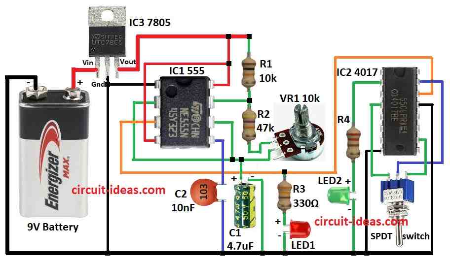
How to Build:
To build a Frequency Divider Circuit follow the below mentioned steps for connections:
- First, pin 1 of IC1 555 connects to ground.
- Next, pin 2 connects to pin 6 using capacitor C1.
- After that, pin 3 of IC1 connects to pin 15 of IC2 4017.
- Then pins 4 and 8 of IC1 connects to +9V battery.
- Now pin 5 connects to ground using capacitor C2.
- Also, resistor R2 connects between pin 7 and top leg of VR1 pot.
- Lastly, resistor R1 connects between pin 7 and +9V and also resistor R3 + LED1 connect in series from pin 3 to ground.
VR1 potentiometer and SPDT switch connection:
- First, one leg connects to R2 and other leg connects to pin 2 and pin 6, also add resistor R4 + LED2 connects in series from pin 2 of IC2 to ground.
- Then pin 4 of IC2 connects to 3rd leg of SPDT switch.
- After that, pins 8 and 13 of IC2 connects to ground.
- Now pin 10 connects to 1st leg of SPDT switch and pin 15 connects to center leg of SPDT switch.
- Also, pin 14 connects to pin 3 of IC1.
Power using IC3 7805:
- Connect the Vin pin to the +9V battery, connect the GND pin to the negative supply and connect the Vout pin to the positive supply pin of the IC1 circuit; the regulator then provides a regulated 5V supply to the circuit.
Safety Tips:
- Check wires and parts connected tight and right and do not leave live circuit alone especially when connected to other devices.
- If unsure ask someone skilled or use trusted guides online and be careful as wiring helps avoid damage or shock.
Conclusion:
To conclude, this easy Frequency Divider Circuit uses IC 555 to make signal with adjustable frequency; also IC 4017 counts signal and skip pulses to divide frequency.
Furthermore, by linking reset pin to different output Q pin, we can divide frequency by 2, 3, 4, etc; also it is a very easy way to learn how frequency divider works using common ICs.