This Simple Hum Free Regulator Power Supply Circuit uses one common transistor 2N3055 to make power supply clean and stable; also it stops unwanted noise like hum sound which sometimes come from power supply.
What is a Hum Free Regulator Power Supply:
A Hum Free Regulator Power Supply circuit reduces or removes hum noise that usually comes from the power supply and it also provides steady and controlled voltage to electronic devices.
Mostly this circuit uses filter and voltage control parts to give clean and stable power and to reduce trouble in easy audio or electronic works.
Circuit Working:
Parts List:
| Components | Values | Quantity |
|---|---|---|
| Resistor | 1k 1/4 W CFR | 1 |
| Capacitors | 10µF 50V Electrolytic | 2 |
| 220µF 50V Electrolytic | 1 | |
| Semiconductor | Transistor 2N3055 | 1 |
| Diode 6A4 | 1 | |
| Transformer 0-25V 5 Amp | 1 |
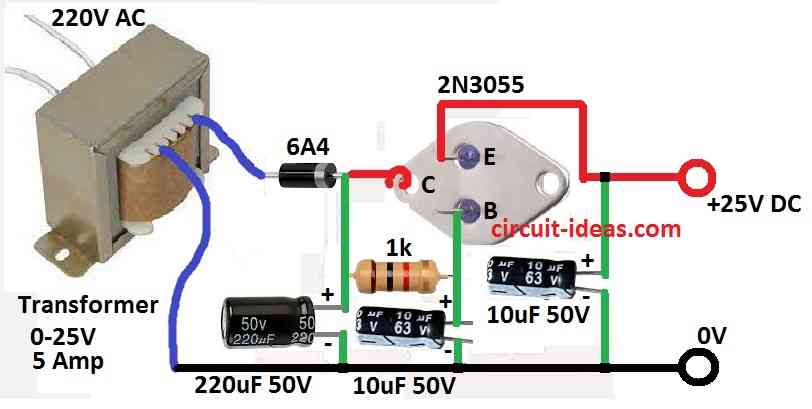
To begin with, this circuit uses 25V 5A transformer to give AC voltage output.
One 6A4 diode changes AC voltage into pulsing DC voltage and then 220uF capacitor smooth the pulsing DC and gives around 30V stable DC.
Also, this 30V DC connects to collector pin of 2N3055 transistor and the base of transistor connects to 30V line using 1k resistor, also this resistor give bias to transistor.
Furthermore, one 10uF capacitor connects between transistor the base and ground and this capacitor helps to make clean and steady DC at transistor base.
Moreover, output come from emitter of 2N3055 transistor and this output is hum free and regulated DC voltage.
How Circuit Work:
The 1k resistor give bias to 2N3055 so it can control output voltage and 10uF capacitor work like filter.
Also, it remove AC ripple and noise from 30V line, so base of transistor gets steady DC voltage.
2N3055 work as emitter follower and it gives output voltage almost same like base voltage but with low impedance.
Hence, this keep output voltage steady and clean and also audio amplifier connects to this output, so audio sound is clean and with no hum noise.
Why This Circuit is Good:
Output from 2N3055 is clean and with no hum sound because of 10uF capacitor.
2N3055 transistor keeps output voltage stable and work like emitter follower and power supply is very useful for audio circuit because it give clean DC voltage.
Safety:
Always use right parts with correct ratings and also take care and follow safety when building the circuit.
Formulas:
When making a hum-free power supply circuit, we must ensure proper voltage control, filtering and heat management.
Below is some basic formula:
Base Resistor R:
To set base current for 2N3055 transistor uses this formula:
R = (Vdiode – VBE) / IB
where:
- Vdiode is voltage from diode for example: 15V if output is 15V
- VBE is base emitter voltage of 2N3055 which should be around 2V
- IB is base current it should normally be 1/10 of output current
This help to choose correct resistor value for giving proper base current to 2N3055.
How is the Circuit Build:
To build a Simple Hum Free Regulator Power Supply Circuit follow the below mentioned connection steps:
Input Stage:
- First, connect breadboard to 25V 5A transformer.
- Also, from transformers secondary side connect to 6A4 rectifier diode to change AC to DC.
- Then from diodes output the positive side connects to breadboards positive supply.
- And from diodes negative side connect to breadboards negative GND supply.
- After that connect positive supply to positive leg of 220uF capacitor and connect negative leg of capacitor to negative supply GND.
Regulator Stage:
- Connect positive side of 220uF capacitor to collector pin of 2N3055 transistor.
- Connect emitter pin of 2N3055 to ground line.
- Base pin of 2N3055 connect to positive supply using 1k resistor.
- Also connect 10uF capacitor between base of 2N3055 and ground.
- Check twice all connections and also ensure they are correct and safe.
- Now turn ON the circuit.
- Use multimeter and check output voltage between ground and emitter pin of 2N3055.
- Check if output voltage is stable and if not then adjust input voltage a bit.
- Also, if want to check steady voltage at base of 2N3055 then measure across the 10uF capacitor.
Important Things to Remember:
- Be sure transistor pinout collector, base, emitter is correct.
- Watch diode and capacitor polarity with plus and minus side.
- Check for short circuits.
- Be sure soldering is good and safe.
- Start testing with low voltage to avoid damage.
Conclusion:
Overall, this Simple Hum Free Regulator Power Supply Circuit is only simple guide but the actual circuit may change little bit based on parts or datasheet.
Also, if anyone is not sure about any part ask experienced person or use good tools or manuals.
Remember, safety is always first while working with electronics.
Leave a Reply