This LED Chaser Circuit using IC 4017 project make LED lights turn ON one by one like chasing.
It is fun way to learn electronics.
One chip of IC 555 makes pulse again and again.
That pulse connects to other chip IC 4017 and it turn ON and OFF each pin one by one.
All pins connect to LED so LED blink one after other.
We can change speed of LED chase by turning one knob.
This circuit is good for beginners and we can learn how, two important chips work.
Like small course to show how LED lights in order.
What is a LED Chaser Circuit using IC 4017:
LED chaser circuit with IC 4017 is very popular and easy which make nice light effect by turning ON and OFF LEDs one by one like chasing.
IC 4017 is also call decade counter.
It is useful chip mostly used in LED chaser circuits.
Circuit Working:
Parts List:
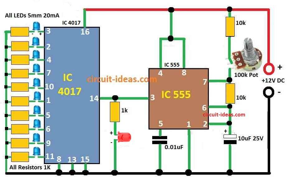
| Type | Specification | Quantity |
|---|---|---|
| Resistors | 1k | 11 |
| 10k | 2 | |
| Potentiometer 100k | 1 | |
| Capacitors | PPC 0.01µF | 1 |
| Electrolytic 10µF 25V | 1 | |
| Semiconductors | IC 4017 | 1 |
| IC 555 | 1 | |
| LEDs 5mm 20mA | 11 |
IC 555 work as astable multivibrator that mean it make square wave pulse again and again with no stop.
One knob potentiometer connect between plus positive and ground.
Middle pin wiper of knob connects to pin 6 of IC 555.
This help to change voltage on pin 6 so it can change how fast IC 555 make pulse.
IC 4017 is called decade counter and it have 10 output pins from pin 3 to pin 11.
Pin 14 of IC 4017 clock input connect to pin 3 of IC 555 output.
So every time IC 555 send a pulse IC 4017 connects to next output pin.
10 LEDs connect to output pins of IC 4017.
When clock pulse come IC 4017 turn ON each LED one after one and this makes LED chasing or running light effect.
Knob potentiometer in IC 555 part control speed of pulse.
When we turn knob it changes how fast capacitor charge and discharge in IC 555 and that changes the pulse speed.
So LED chase goes fast or slow depending on knob setting.
How circuit works:
IC 555 make square wave signal again and again and knob changes how fast it make.
This signal goes to IC 4017 clock input and IC 4017 turn ON each output in order.
LEDs connect to these output pins so they light up one by one like chasing.
Whole circuit uses 12V DC power.
Speed Control:
We can turn knob to make LED go faster or slower.
Knob changes the resistance and that change the timing in IC 555.
More resistance = slower chase and Less resistance = faster chase.
Formulas:
Formulas for LED Chaser Circuit:
1. Frequency of IC 555 Astable Multivibrator:
This show how fast IC 555 make square wave signal.
Formula:
f = 1.44 / (RA + 2 × RB) × C
where:
- f is the frequency in Hertz Hz
- RA is the resistor which connect to pin 7
- RB is the resistor which connect to pin 6 and 2
- C is the capacitor that connect to pin 6 and 2
This formula tell how fast LEDs will blink one by one.
2. LED Current Limiting Resistor:
Each LED needs a resistor so it does not burn.
Formula:
RLED = VR / ILED
where:
- VR is the voltage from 12V minus LED forward voltage
- ILED is how much current LED should get
Use this to keep LED safe.
3. Duty Cycle of IC 555:
Duty cycle means how long output stay HIGH ON compared to LOW OFF.
Formula:
D = RB / (RA + 2 × RB)
This show how much time output is ON in one full cycle.
How the Circuit is Build:
To build a LED Chaser Circuit using IC 4017 follow the below steps for connections:
IC 555 Connections:
- Pin 1 connects to ground.
- Pin 2 connect with resistor to pin 6 and capacitor to ground.
- Pin 3 connects to pin 14 of IC 4017 which is the clock input.
- Pin 4 and pin 8 connect to VCC of positive power.
- Pin 5 connect to ground with 0.1µF capacitor.
- Pin 6 connect to one side of 10k resistor.
- Pin 7 connect to one end of 100k potentiometer knob.
IC 4017 Connections:
- Pin 8, 13 and 15 connects to ground.
- Pin 16 connect to 12V power.
- Pins 3 to 11 are output pins which connects each to one LED.
- Anode of LED long leg connects to IC 4017 output pin 3 to 11.
- Cathode of LED short leg connects to ground through 1k resistor.
Notes:
- Use correct resistor so LED does not get too much current.
- Double check IC pins and LED direction before power is ON.
- Turn potentiometer to change speed of chasing LED effect.
Conclusion
This easy and LED Chaser Circuit using IC 4017 first should try it on breadboard before making permanent on PCB.
Always be careful when working with electric circuits and safety should be first.
For more details we can look at datasheet of the ICs and learn how the circuit work.
Leave a Reply