This Ornamental Flashing LEDs Circuit makes LEDs blink nice way, as it have a tiny timer chip to control ON and OFF blink.
Also, we can use blinking LEDs to decorate, art or to attract people and if we can change the speed and the order of LED blink we can get different style and effect, which makes things look more good.
Circuit Working:
Parts List:
| Components | Values | Quantity |
|---|---|---|
| Resistors ( All resistors are 1/4 watt unless specified) | 10k | 1 |
| 1M | 1 | |
| 470Ω | 1 | |
| 100Ω | 1 | |
| Capacitors | Ceramic 10nF | 1 |
| Electrolytic 1µF 25V | 1 | |
| Electrolytic 220µF 16V | 1 | |
| Semiconductors | IC 555 | 1 |
| LEDs Red 5mm 20mA | 3 | |
| LEDs Green 5mm 20mA | 3 | |
| LEDs Yellow 5mm 20mA | 3 |
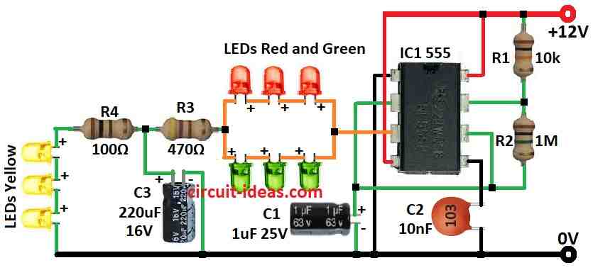
This circuit make nice light display by blinking 3 LED groups in different speed, as it use simple astable multivibrator with 555 timer IC and very common chip.
Also, blink speed depend on resistors R1, R2 and capacitor C1.
First red LEDs turn ON when output is high, then after some time yellow LEDs turn ON as time depend on C3 capacitor and when output goes low green LEDs turn ON using power from capacitor.
Hence, this fast change make cool flashing effect and if green LEDs is too bright then just use only one LED to make it less strong.
Formula:
We can use this formula to find how fast LED blink with 555 timer in astable mode:
Frequency (f): f = 1.44 / (R1 + 2R2) × C
where:
- R1 is resistor between pin 7 discharge and Vcc.
- R2 is resistor between pin 6 threshold and pin 7.
- C is total capacitor value from C1.
Note:
With 555 chip this simple setup makes nice LED blink pattern, as it is easy and works good and we can change parts to fit our own idea or project.
How to Build:
To build a Ornamental Flashing LEDs Circuit we need to follow the below mentioned connections steps:
- First, put NE555 timer IC on the PCB board.
- Next, connect pin 8 of IC to positive power side of PCB.
- Then connect pin 1 of IC to ground and to negative power side.
- Join pin 4 to pin 8 and both connects to positive power.
- Also, connect pin 7 to pin 6 and pin 2.
- Put 10k resistor R1 and 1M resistor R2 between pin 2 and pin 6.
- Now connect pin 3 output to 6 LEDs.
- Also, connect a 1µF capacitor C1 from pin 2/6 to ground.
- Connect C3 between point of R3 and R4 and ground.
- Then put 10nF ceramic capacitor C2 between pin 5 and ground.
- Lastly, connect 3 yellow LEDs through resistor R4 to ground.
Note:
- At the end give power to circuit with 5V to 12V DC, circuit will start blinking LEDs in pattern and if blink speed is not good then change resistor and capacitor values to get what we want.
Conclusion:
To conclude, Ornamental Flashing LEDs Circuit is easy and nice way to make lights look good, as it uses timer IC to control when LEDs blink and how they blink.
Furthermore, we can make many cool light effects which are good for decoration; hence, this circuit is good for many projects to make them look more pretty.
Leave a Reply