This Public Address Amplifier Circuit it works like a very strong loudspeaker for our voice!
When we speak on microphone then it makes our voice go very loud because of that many people can hear us good.
Good for big place like school, office, stadium or parties where we want all people to hear same thing.
Circuit Working:
Parts List:
| Category | Item | Quantity |
|---|---|---|
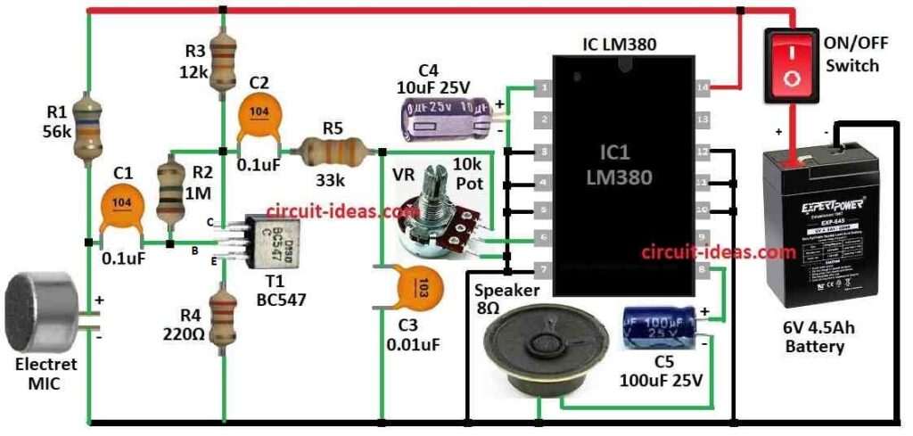
| Resistors | 56k | 1 |
| 1M | 1 | |
| 12k | 1 | |
| 220Ω | 1 | |
| 33k | 1 | |
| Potentiometer 10k | 1 | |
| Capacitors | Ceramic 0.1µF | 2 |
| Ceramic 0.01µF | 1 | |
| Electrolytic 10µF 25V | 1 | |
| Electrolytic 100µF 25V | 1 | |
| Semiconductors | IC LM380 | 1 |
| Transistor BC547 | 1 | |
| 8Ω Speaker | 1 | |
| ON/OFF Switch | 1 | |
| Electret MIC | 1 | |
| Battery 6V 4.5Ah | 1 |
This circuit is for using like public speaker system which is very useful in noisy place.
It helps to talk without shouting.
It uses one LM380 chip, this chip give 2 watt power and is good for talking in open area or public place.
Circuit comes in small size where we can put all parts like speaker and battery in one box which is easy to carry.
First part of circuit is preamplifier it uses one NPN transistor BC547 and the second part is power amplifier using LM380 chip.
We can connect collar mic (clip mic) to circuit using audio jack.
Our voice go through transistor T1 first then goes to LM380 input with volume control VR.
One capacitor C3 is used to stop bad noise like howling from speaker.
LM380 chip is strong and good audio amplifier it gives 34 dB gain and is also safe from short circuit and heating.
It work with 5V to 22V DC power.
This chip comes in small dual pin body.
For making circuit we can use normal PCB.
For small size use 9V battery (PP3) but for long use better to use 6V 4.5Ah rechargeable battery.
Also we need to add a charging option.
Use good quality small 8 ohm speaker.
If sound is not loud enough we can change LM380 with more powerful amplifier chip.
How to Build:
To build a Public Address Amplifier Circuit we need to follow the below mentioned connections steps:
Preparation:
- Collect all parts and tools before starting soldering and constructing.
Circuit Design:
- See the circuit diagram for amplifier.
- Try to understand all wire and part connection.
PCB Layout:
- Design or get PCB layout same like diagram.
- This help us put all parts in right place.
Component Placement:
- First put IC socket and then add resistor, capacitor, transistor and other parts on PCB by circuit design.
Soldering:
Wiring:
- Connect mic, volume knob audio jack and speaker to right place on PCB same as diagram.
- After finish making test with battery and sound input check it is working or not.
Enclosure:
- If one wants to put circuit on PCB and put battery and all parts inside one box like speaker box, this will make it safe and easy to carry.
Final Testing:
- Test again after putting inside box and be sure all works good.
Finalization:
- Fix all the wires are strong and write name on switch, input and volume if needed.
Note:
- Always be careful when use solder and electric things.
- If one is not sure about electronics better ask help from someone who know it better.
Conclusion:
Main goal of Public Address Amplifier Circuit is to make sound from mic or other input go louder so people can hear clearly from speaker.
How big and how strong the PA amplifier should be depend on place size and how much noise is around.
Leave a Reply