In many electronic circuits, wrong battery connection can damage sensitive components, therefore, a Simple Reverse Polarity Protection Buzzer Alarm Circuit gives an early warning before damage happens.
This circuit is simple, low cost and easy to build, also it uses common parts like diode, resistor, LED and buzzer.
When we connect the supply in the correct way, the circuit stays normal and however, when we connect the battery in reverse the buzzer and LED give an alert immediately.
Circuit Working:
Parts List:
| Components | Values | Quantity |
|---|---|---|
| Resistor | 1k 1/4 watt | 1 |
| Semiconductors | Any standard LED | 1 |
| Diode 1N4001 | 2 | |
| Piezo Buzzer | 1 | |
| Power Supply DC Input Source | 1 |
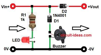
First, connect the positive supply to Vin and negative to GND.
During correct polarity:
The current flows from Vin to Vout through diode D2 and this D2 allows forward current flow.
So the output gets supply voltage and at the same time the D1 blocks the current path to the buzzer and therefore, LED and buzzer remain OFF.
Now during reverse polarity:
The battery terminals get connected in the wrong direction, as a result D2 blocks current toward the load and protects the output side.
Meanwhile, D1 becomes forward biased and then current flows through D1 and the piezo buzzer, so the buzzer starts sounding.
At the same time the LED1 glows through resistor R1 and hence, the user gets both sound and visual warning.
In short, this circuit warns the user and also helps protect the load circuit.
Important note:
The LED is intentionally connected in reverse polarity so that it glows only when the battery or DC input is connected in the wrong direction.
By connecting the LED anode to Ground and the cathode to the resistor (which goes to the positive input), the LED will only illuminate when the positive and negative supply lines are reversed.
Formula with Calculation:
- Formula for resistor calculation for LED:
Use Ohms Law:
R = (Vs – Vled) / Iled
where:
- R is resistor value
- Vs is supply voltage
- Vled is LED forward voltage
- Iled is LED current
Example for 12V supply calculation:
Assume:
Vs is 12V
Vled is 2V
Iled is 10mA = 0.01A
R = (12 – 2) / 0.01
R = 10 / 0.01
R = 1000 ohms
So,
R = 1k ohm
This resistor value matches our circuit diagram.
2. Power dissipation of resistor:
P = V × I
where,
- P is the power
- V is the Voltage
- I is the Current
P = 10 × 0.01
P = 0.1W
Therefore, we have used a 1/4 watt resistor safely.
How to Build:
To build a Simple Reverse Polarity Protection Buzzer Alarm Circuit following steps are needed for connection:
- Start, the circuit by assembling all the circuit parts as per diagram above.
- Next, take diode D1 and connect anode to buzzer positive side and connect cathode to main positive line.
- Then take, diode D2 and connect anode to Vin line and connect cathode to Vout.
- After that, take resistor R1 and connect one end to Vin line and other end connect to LED cathode.
- Then take, LED and connect anode end to resistor output and connect cathode end to GND.
- Next, take Piezo buzzer and connect positive pin to D1 anode and negative pin to GND.
- Lastly , power Supply positive terminal goes to to Vin and negative terminal to GND.
Note:
This circuit is not harmful for low-voltage DC electronics use and in fact it helps protect our main circuit.
However, it becomes risky if we use for:
- high voltage
- high current load
- wrong wiring
- AC mains supply
For best safety, use this circuit only in 5V–12V DC small electronic projects.
Conclusion:
This Simple Reverse Polarity Protection Buzzer Circuit gives fast warning when someone connects the battery in the wrong direction.
Also, it protects the output load using diode D2, moreover the LED and buzzer make fault detection easy.
Since the design uses only a few components the beginners can build it without difficulty and therefore, this circuit is a good choice for small electronic protection projects.
Leave a Reply