Stun Gun Circuit using IC 555 is simple electric device which make high voltage for non-lethal self defense.
Remember, before making it we must know the danger and law rules to follow.
Circuit Working:
Parts List:
| Components | Values | Quantity |
|---|---|---|
| Resistors | 33k, 1k 1/4 watt | 1 each |
| Capacitors | Ceramic 10nF, 100nF | 1 each |
| PPC 10nF 400V | 8 | |
| Semiconductors | IC 555 | 1 |
| Transistor BD679 | 1 | |
| Diode 1N4007 | 8 | |
| Transformer primary resistance 8 ohms (0.5 mm super enameled copper wire) Secondary winding resistance 1000 ohms (0.5 mm super enameled copper wire) | 1 | |
| Push button | 1 |
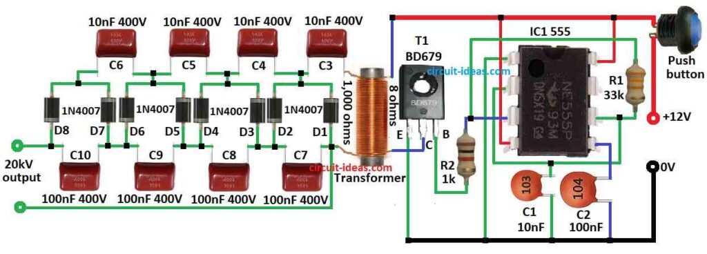
To begin with , the 555 IC work as astable multivibrator and it makes square wave signal and give high voltage pulse for stun gun.
How circuit work:
555 timer makes square wave when in astable mode and this signal goes to transformer.
Furthermore, the transformer uses an 8-ohm primary coil made of 0.5 mm copper wire, then, the transformer boosts the voltage to several kilovolts (kV).
Diodes change AC to DC and capacitors smooth the output and final output is 20kV where 2 metal points and electrodes gives stun shock.
Also, capacitor C1 charge by R1 and R2 and when C1 reaches 2/3 voltage then 555 IC flip output.
Then C1 discharge through R2 and when voltage goes below 1/3 then output flips again and this repeat make square wave.
Hence, the transformer boosts this waveform, additionally, the secondary coil has a resistance of 1000 ohms and uses 0.5 mm wire.
Diodes D1 to D8 rectify high voltage, capacitors C3 to C10 smooth the output and final 20kV output used for stun shock with electrodes.
Formulas:
To make high voltage pulse for stun gun we need high frequency from 555 IC in astable mode.
Formula for Frequency (f):
f = 1.44 / (R1+2*R2)*C
where,
- R1 and R2 are the resistors
- C is the capacitor
D = R2 / R1+2*R2
For good result D > 50%
By changing R1, R2 and C we set needed frequency and duty cycle for stun effect, also it depend on transformer type and circuit needs.
Cockcroft Walton Multiplier (CW):
CW is ladder of capacitors and diodes and it changes low AC or pulsed DC into very high voltage.
Output Voltage:
Vout = n * Vpeak
where,
- n is the number of stages
- Vpeak is the peak of input wave
The CW circuit generates very high voltage for a stun gun, but however, high voltage can cause serious injury, so always follow proper safety precautions when using this circuit.
How to Build:
To build a Stun Gun Circuit using IC 555 follow the below mentioned steps for connections:
- First, collect all parts like shown in circuit diagram.
- Next, connect pin 1 of IC 555 to ground.
- Then connect pin 2 to pin 6 and also put capacitor C1 from pin 2 to ground.
- After that, connect pin 3 to base of transistor T1 through resistor R2.
- Now connect pin 4 and pin 8 of IC to 12V positive.
- Also, connect pin 5 to ground using capacitor C2.
- Then connect pin 6 to pin 3 through resistor R1.
- Next, connect emitter of T1 to ground, connect collector of T1 to 8 ohm transformer coil and then connect base of T1 to pin 3 of IC 555.
- Also, connect 8 diodes D1to D8 and 8 capacitors C3 to C10 in cascade to make high voltage multiplier.
- Lastly, add push button to 12V positive line.
Safety Notes:
- Follow all local laws for stun guns and use only for legal and safe purpose.
- Always use with care and avoid dangerous use.
Conclusion:
Overall, Stun Gun Circuit using IC 555 is simple circuit to make, as it gives high voltage output for non-lethal self defense; but we should always be careful and follow law and safety rules.
the coil is going to be huge isn’t it? Not impractical?