Temperature Based DC Fan Controller Circuit using Transistors turns ON when hot, stops overheating and saves energy.
Thermistor checks temperature and runs fan as needed.
The circuit works on 12V battery or 12V power supply.
Circuit Working:
Parts List:
| Component Type | Value | Quantity |
|---|---|---|
| Resistors (All resistors are 1/4 watt unless specified) | 1.5k | 1 |
| 1k | 1 | |
| 270Ω | 1 | |
| 680Ω | 1 | |
| Thermistor NTC 15k at 20°C | 1 | |
| Potentiometer 22k | 1 | |
| Potentiometer 470Ω | 1 | |
| Capacitors | Electrolytic 100µF 25V | 1 |
| Semiconductors | BD140 PNP Transistor | 1 |
| BC547 NPN Transistor | 1 | |
| 12V 700mA DC Fan Motor | 1 | |
| LED 5mm 20mA | 1 |
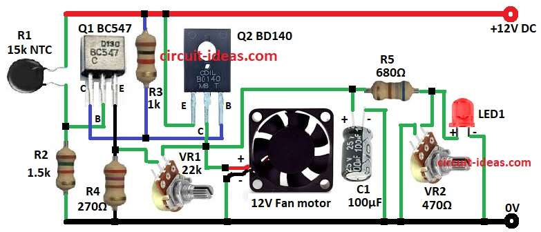
Circuit has two transistors Q1 BC547 and Q2 BD140.
Also it has resistors, capacitor, LED and12V DC fan.
NTC thermistor R1 senses heat with high temperature, with this R1 resistance drops.
Base voltage of Q1 goes up, Q1 conducts and turns ON the transistor Q2.
Q2 powers fan and fan spins and cools system.
LED1 is ON and fan starts running.
Capacitor C1 smooths voltage changes.
VR1 adjusts how Q1 & Q2 switch, avoids false triggers and makes response slowly.
VR2 controls LED brightness and stops burns out.
VR2 and C1 give slight delay to fan start which avoids sudden voltage jumps.
Formulas with Calculations:
Voltage divider for Q1 base:
V_B1 = V_CC × (R2 / (R1 + R2))
V_CC = 12V, R1 = 15k, R2 = 1.5k
So V_B1 = 1.09V
LED current resistor:
R_total = R5 + VR2 = 680Ω + 470Ω = 1150Ω
LED current:
I_LED = (V_CC – V_LED) / R_total
V_LED = 2V → I_LED = (12V – 2V) / 1150Ω = 0.0087A = 8.7mA
Note:
8.7mA is OK
Typical LED runs from 10 to 20mA, but this is a bit lower so its safe.
How to Build:
To build a Simple Temperature Based DC Fan Controller Circuit using Transistors follow the below steps for connections and assembling:
- Put parts like in circuit diagram.
- Base of Q1 goes to one end of NTC R1 and other end R1 goes to +12V.
- Emitter of Q1 connect to one end of VR1 and other end of VR1 goes to collector of Q2.
- Collector of Q1 connects to one end of R3 and other end R3 goes to +12V.
- R2 connects between base of Q1 and GND.
- Emitter of Q2 connects to +12V supply.
- Base of Q2 goes to collector of Q1.
- R4 from emitter of Q1 connects to GND.
- Collector of Q2 goes to one end of 12V fan and other end fan goes to GND.
- Positive of C1 goes between fan and one end of R5 and other end of R5 to VR2 and its negative of C1 goes to GND.
- Other end of VR2 goes to GND.
- LED anode goes from VR2 end and LED cathode goes to GND.
Conclusion:
In this post for Temperature Based DC Fan Controller Circuit using Transistors, when hot the thermistor makes Q1 change, Q2 turn ON and fan run.
LED shows fan ON.
The circuit works simple, cheap and is easy to build.
Change resistors or thermistor to set turn ON temperature.