This is a simple and low-cost Solar Sensor Based Security Alarm Circuit using Transistors which uses a solar sensor for light sensing.
The circuit gives alarm sound through the speaker when light level changes and it works mainly when darkness comes or when someone blocks light on the sensor.
So we can use this circuit for door safety, cupboard alarm, showcase protection and small night warning systems.
Also, the circuit works with a 9V battery supply and it uses only a few components, so it is easy to build and easy to carry.
Circuit Working:
Parts List:
| Components | Specification | Quantity |
|---|---|---|
| Resistors (All resistors are 1/4 watt) | 10k, 100k, 1k, 68k, 1.2k, 120Ω | 1 |
| Capacitors | Ceramic 0.047µF | 1 |
| Electrolytic 33µF 25V | 1 | |
| Semiconductors | Transistor NPN BC547 | 1 |
| Transistors NPN BC337 | 2 | |
| Transistor PNP BC327 | 1 | |
| Any standard LED | 1 | |
| Diode 1N4148 | 2 | |
| Speaker 8Ω | 1 | |
| Solar Cell 2V to 3V 50mA | 1 | |
| Power supply 9V or battery | 1 |
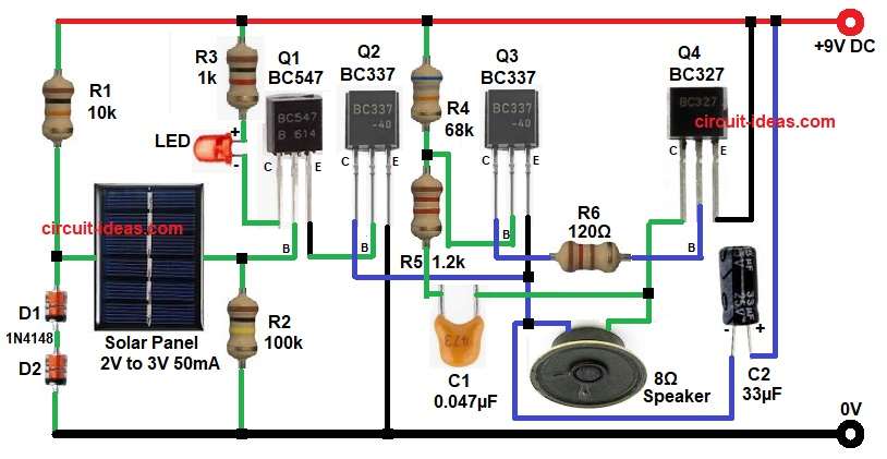
First, the solar cell senses the light intensity and when light falls on the sensor, it produces a small voltage or current, this signal goes to the base of transistor Q1 BC547.
Next, Q1 works like the first switching transistor and when the light level changes, Q1 turns ON and sends the signal to transistor Q2 BC337 and then Q2 increases the current gain.
After that, transistor Q3 BC337 works as a driver stage and it helps to amplify the signal further and sends it to Q4 BC327 through resistor R6.
Then Q4 BC327 which is a PNP transistor drives the 8 ohms speaker and as a result, the speaker produces an alarm sound.
Meanwhile, capacitor C1 helps in sound pulse generation and improves oscillation and capacitor C2 filters the supply and gives stable operation.
Also, LED1 glows as an indication that the circuit is active.
How to Build:
To build a Solar Sensor Based Security Alarm Circuit using Transistors follow the below connection steps:
- Start, the circuit first by collecting all the parts as shown in diagram above.
- Next, start with transistor Q1 BC547 and connect base pin to one end of solar sensor output and R2 resistor network.
- Then collector pin goes to LED and and resistor R3.
- And emitter goes to base pin of transistor Q2.
- Then start with transistor Q2 BC337 and connect base pin to emitter pin of Q1.
Emitter pin goes to ground. - And collector pin goes to emitter of Q3 and one end of speaker line and negative of capacitor C2.
- After, that take transistor Q3 BC337 and connect base pin between R4 and R5 resistor network.
- Then collector pin connect to base pin of transistor Q4 through resistor R6.
- And emitter pin connects to collector of transistor Q2.
- Next, take last transistor Q4 BC327 and connect emitter pin to +9V power supply.
- Then base pin goes to collector of transistor Q3.
- And collector pin goes to speaker one end and capacitor C1 one end.
- Then start, with resistor R1 and connect from positive supply line and to one end of solar cell.
- Solar cell one end connect to diodes D1 and D2 in series and ground.
- Speaker 8 ohm one end connect from junction of capacitor C1 one end and collector of transistor Q4 and other end of speaker goes to junction of emitter Q3 transistor and collector of transistor Q2.
Conclusion:
To conclude, this Solar Sensor Based Security Alarm Circuit using Transistors gives a useful and low-cost solution for darkness or shadow detection.
Moreover, the transistor stages provide good amplification and strong sound output and because the circuit uses common components, we can build it easily on a general PCB or breadboard.
Finally, this project is very good for beginners, school electronics projects and simple security alarm applications.