Today, in advanced world electronic touch switches are becoming very popular.
They replace mechanical switches and therefore, there is no moving part, so its life is longer.
This Touch ON OFF Switch Circuit using IC 555 Timer works as a bistable multivibrator.
When we touch the touch point the output changes its state, that means output becomes ON or OFF alternately.
The circuit is simple and also its cost is low and it can operate from 5V to 12V DC supply.
Circuit Working:
Parts List:
| Components | Values | Quantity |
|---|---|---|
| Resistors | 470k, 1M 1/4 watts | 1 each |
| Preset 1M | 1 | |
| Capacitor | Ceramic 0.01uF | 1 |
| Semiconductors | Touch Pads Metal touch points | 2 |
| 555 Timer IC | 1 | |
| Power Supply 5V to 12V DC | 1 |
When power is given the circuit is ready to function but initially the output may be LOW or HIGH.
Pin 2 (Trigger) and Pin 6 (Threshold) are very important as they control the flip of output.
When a person touches the first touch point the small voltage enters pin 2.
Human body acts like antenna, so it captures noise and small AC voltage and this makes trigger pin voltage go below 1/3 Vcc.
Therefore, output at pin 3 becomes HIGH but now output stays HIGH, it will not change automatically.
When user touches second touch point connected to pin 6, voltage at threshold pin increases above 2/3 Vcc and therefore output becomes LOW.
So every touch changes the state and thus it acts like toggle switch.
R1, R2 and VR1 help to increase sensitivity and C1 removes noise and gives stability.
How to Build:
To build a Touch ON OFF Switch Circuit using IC 555 Timer following are the steps we need to follow:
Start, the circuit first by collecting all the components as per the diagram above.
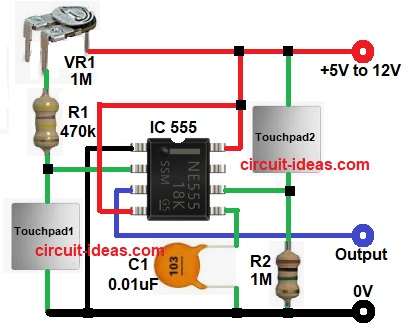
Then start with IC pin 1 which goes to GND
Pin 2 trigger pin connect to one end of R1 and one end of touch point1.
Pin 3 output pin connect to output.
Pin 4 reset pin connect directly to Vcc.
Pin 5 control voltage pin connect 0.01uF capacitor to ground for noise filtering.
Pin 6 threshold pin connect to R2 one end and second touch point one end.
Pin 8 is Vcc pin connect to +5V to +12V DC supply.
Connect VR1 resistor one end to R1 one end and other end of VR1 goes to positive supply.
Conclusion:
This Touch ON OFF Switch Circuit using IC 555 Timer is simple and useful project.
It uses 555 in bistable mode and therefore output changes state with every touch.
Human body provides small trigger voltage, high value resistors increase sensitivity and also capacitor removes noise.
It works from 5V to 12V,so it is good for many low voltage applications.
Because of simple design the beginners can easily build it as it is good learning project and for understanding 555 timer working.
Leave a Reply