This project is for Transistor Based 12V Emergency Light Circuit system, which gives light when main power fails.
The circuit uses transformer, bridge rectifier, transistor, relay, battery and few other components.
When AC supply is present, battery charges and lamp stays OFF and when AC power goes OFF then battery gives supply and lamp turns ON automatically.
This circuit is useful for home and small places where there is power failures.
Circuit Working:
Parts List:
| Components | Values | Quantity |
|---|---|---|
| Resistors | 2.2k, 3.3k 1/4 watts | 1 each |
| 100Ω 1/4 watt | 2 | |
| Capacitors | Electrolytic 1000µF 25V | 1 |
| Transistor TIP41C | 1 | |
| Any standard LED 5mm | 1 | |
| Bridge Diode 1N4001 | 4 | |
| Diode 1N4001 | 1 | |
| Zener Diode 15.6V 1W | 1 | |
| Transformer Primary 220V AC, Secondary 0V-15V | 1 | |
| Fuse 1A | 1 | |
| Switch On/Off SPST | 2 | |
| Lamp 12V | 1 | |
| Battery 12V | 1 | |
| Relay 12V 5A | 1 |
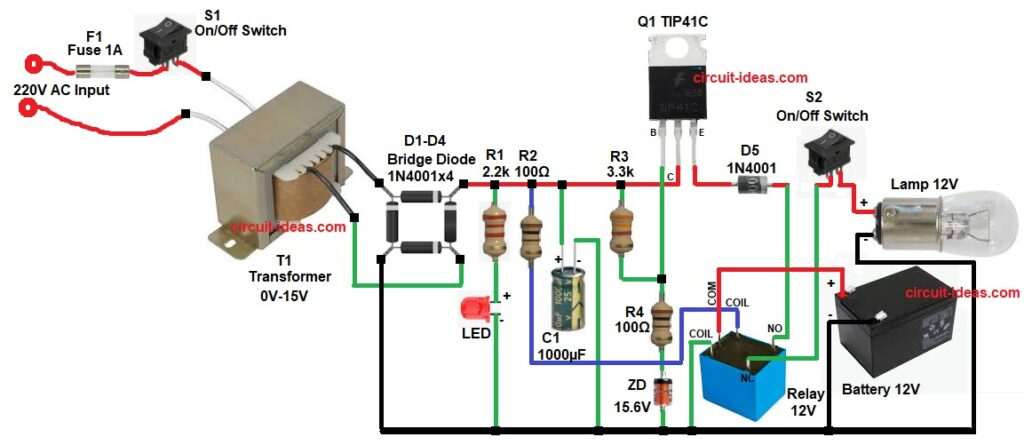
In this circuit, the 220V AC supply goes to transformer through fuse and switch S1 for protection and this transformer steps down voltage to 15V AC.
Then bridge rectifier converts AC to DC, capacitor filters the DC and makes smooth voltage.
This DC supply charges the battery through resistor R3 and diode D5 and LED shows charging indication.
Transistor works like switch, when AC power is present then transistor gets bias and 12V relay COIL pin gets energized, so relay COM pin stays in normal position and lamp does not glow.
When AC power fails then transistor loses bias, relay COIL de-energizes and relay COM changes position, so battery connects to lamp and the lamp turns ON.
Zener diode controls voltage and protects battery from over voltage.
How to Build:
To build a Transistor Based 12V Emergency Light Circuit follow the below connection steps:
- First, start by collecting all the circuit parts as in circuit diagram above.
- Then start with transformer primary and connect to 220V AC with switch and fuse and secondary goes to 15V AC output
- Then with bridge rectifier D1 to D4 connect 4 diodes in bridge form and AC input goes to two opposite terminals and DC output from remaining two terminals.
- After that resistor R1 and LED connect in series with LED anode to show power indication and LED cathode goes to GND.
- Then connect in series resistor R2 and one COIL pin of 12 relay to DC supply and other COIL pin to GND.
- The with capacitor C1 positive connect to DC positive and negative to ground.
- After that start with transistor Q1 emitter pin connect to 12V lamp end through diode D5, relay 12V NO and NC pin and switch S2.
- Collector pin connect to connect to resistors and capacitor network.
- Base connect through resistor network R3 and R4.
- Relay 12V COM pin connect to positive of 12V battery and negative of battery goes to GND.
- Zener Diode cathode connect across resistor R4 and R3 and base of transistor Q1 and anode connect to GND.
- Finally, 12V lamp connect to switch S2 one end and other end of lamp connect to GND.
Conclusion:
This Transistor Based 12V Emergency Light Circuit gives simple and low cost emergency light solution, which works automatic and there is no need of manual switch.
The circuit charges battery and gives backup during power failure.
We can use this circuit at home, shop or small office, as it is easy to build and uses common components which are easily available in market.
Leave a Reply