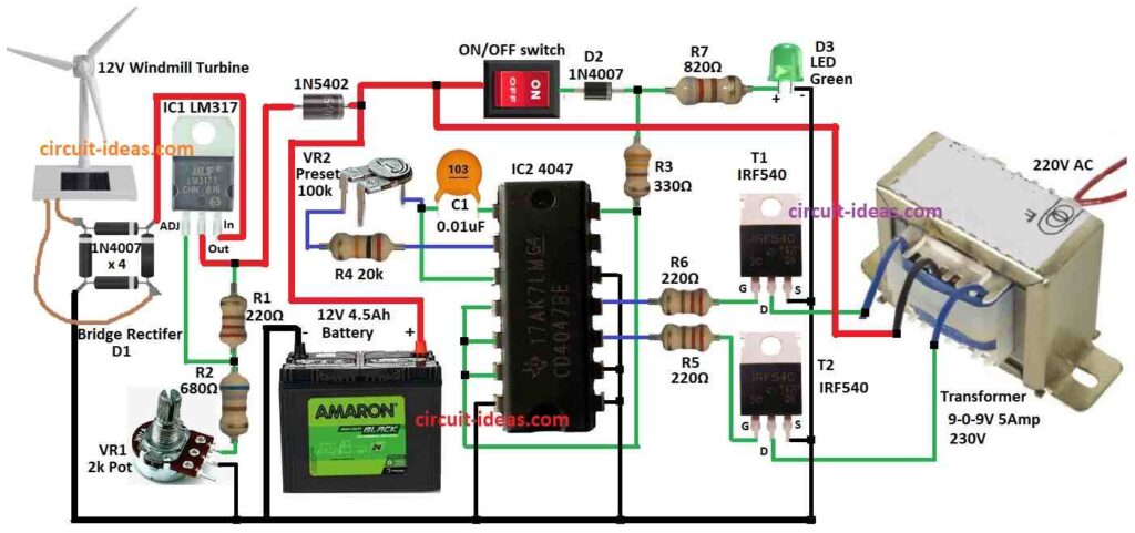
220V Wind Turbine Generator Circuit changes wind energy to useable home power with 220V AC.
We need electricity every day so people try to get it free.
This simple small wind turbine is for home or low power use.
It cost less and give more electricity for the price.
Circuit Working:
Parts List:
| Category | Item | Quantity |
|---|---|---|
| Resistors (All resistors are 1/4 watt unless specified) | 680Ω | 1 |
| 330Ω | 1 | |
| 20k | 1 | |
| 820Ω | 1 | |
| 220Ω | 3 | |
| Potentiometer 2k | 1 | |
| Preset 100k | 1 | |
| Capacitor | Ceramic 0.01μF | 1 |
| Semiconductors | IC1 LM317 or LM338 | 1 |
| IC2 4047 | 1 | |
| MOSFETs IRF540 | 2 | |
| Bridge Rectifier 1N5402 (Substitute for 1N4007 in diagram) | 4 | |
| Rectifier diode IN5402 | 1 | |
| Diode 1N4007 | 1 | |
| ON/OFF Switch | 1 | |
| Green LED 5mm 20mA | 1 | |
| Battery 12V 4.5Ah | 1 | |
| Transformer 9-0-9V 5 Amp 230V | 1 | |
| 12V windmill turbine | 1 |
This small wind turbine can power laptop, electric devices at home or outside.
12V wind turbine make power from wind and it is small and give alternate energy.
Wind power goes to bridge rectifier and controller and then battery charger circuit charge 12V 4.5Ah battery.
Step-up inverter make high voltage AC to run home appliances.
We can choose different 12V wind turbines with different watt power as per our need.
Bridge rectifier change AC to DC and in this circuit 1N4007 diode does this job.
Voltage regulator IC1 LM317 give output from 1.25V to 37V over 1.5A current.
Final DC from regulator goes to 12V 4.5Ah battery and this DC run the inverter circuit.
Formulas
Regulator Output:
LM317 regulator IC1 give output voltage:
Vout = 1.25V × [R2 / (R1 + 1)]
In circuit R2 means R2 + VR1.
Oscillator IC2 4047:
IC2 4047 is low power IC with 14 pins and work as multivibrator to make switching pulse.
Each output pin give 50% duty cycle.
Frequency formula at pin 13:
f = 1 / 8.8RC
here,
R = R4 + VR2 and C = C3
Frequency at pin 10, 11:
f = 1 / 4.4RC
where,
- f in hertz Hz,
- R in ohms and
- C in farads. 4.4 is constant from π (pi).
MOSFET & Switching:
Circuit use IRF540 N-channel power MOSFET by Vishay.
This MOSFET works at high temp with 175°C and fast switching.
Transformer:
Main part of wind turbine output is transformer:
230V primary 9V-0-9V 1.5A center tap secondary and is used in reverse.
MOV (metal oxide varistor) protect output devices.
Voltage Control:
IC1 LM317 get power from wind turbine and adjust output to 12V.
Battery connected through 1N5402 diode to get bias.
Working Process:
When ON/OFF switch is ON:
IC2 4047 work as astable multivibrator and the circuit start to oscillate.
Pin 10 and 11 give 50Hz to IRF540 MOSFET and the power goes to transformer secondary coil.
Output Behavior:
Current does not stay fixed all time it changes.
Coil make EMF (electromagnetic field) and this EMF changes the current.
Output voltage & frequency depend on:
- Number of windings and
- Switching frequency
How to Build:
To build a 220V Wind Turbine Generator Circuit follow the below connections steps:
IC1 LM317:
- Connect adj pin between R1 and R2.
- Connect out pin to diode 1N5402.
- Connect in pin to one leg of bridge rectifier.
IC2 4047:
- Connect pin 1 to pin 3 with capacitor C1.
- Connect Pin 2 goes to resistor R4 and one leg of preset VR2.
- Connect Pins 4, 5, 6, 14 connect between diode 1N4007 and resistor R7 through R3.
- Pins 7, 8, 9, 12 connect to ground.
Transistors (T1 and T2):
- Connect Pin 10 of IC2 to gate of T2 through resistor R5.
- Connect Pin 11 of IC2 to gate of T1 through resistor R6.
- Connect Drain of T1 to first wire of 230V transformer and source to ground.
- Connect Drain of T2 to third wire of transformer and source to ground.
Switch and LED:
- Connect ON/OFF switch, diode D2, resistor R7 and green LED in series to positive of 12V battery.
Bridge Rectifier:
- Connect first leg to IN pin of LM317.
- Connect second & fourth legs to 12V windmill turbine.
- And connect third leg to ground.
Safety Notes:
- Wrong electric work is dangerous more at 220V.
- Use certified wind system for safe working.
- Always double check all wire connections after making circuit.
Conclusion:
220V Wind Turbine Generator Circuit need different safety rules based on size and place.
Better to ask certified electrician or wind energy expert before any setup.
References:
The generator sub-circuit with wind turbine & 3-phase bridge rectifier