Power supply plays a very important role in electronics.
Every circuit needs stable DC voltage and sometimes we need high voltage like 38V DC, so this is the main purpose of this circuit.
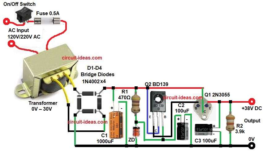
This 38V Linear Power Supply Circuit using Transistors uses 2N3055 and BD139 transistors.
2N3055 is very popular power transistor and it can handle high current and therefore, it is good for power supply design.
And BD139 is a driver transistor which controls and boosts signal and provides enough base current to 2N3055.
In this article, we will understand simple circuit working, with formulas and pin connection step by step.
Circuit Working:
Parts List:
| Components | Value | Quantity |
|---|---|---|
| Resistors | 470Ω ,3.9k 1/4 watts | 1 each |
| Capacitors | Electrolytic 1000uF 50V | 1 |
| Electrolytic 100uF 50V | 2 | |
| Semiconductors | Power Transistor 2N3055 NPN | 1 |
| Driver Transistor BD139 NPN | 1 | |
| Zener Diode 40V 1W or higher | 1 | |
| Bridge Rectifier 1N4002 4A 100V or higher | 1 | |
| Transformer secondary 0V – 30V AC 2A , primary 230V or 120V AC | 1 | |
| Fuse 0.5A | 1 | |
| SPST On/Off Switch | 1 | |
| Heat Sink for 2N3055 | 1 |
First, AC mains 220V enters transformer and switch S1 controls power and use Fuse gives protection.
Then transformer reduces voltage from 220V AC to 30V AC and so voltage becomes safe and usable.
After that 30V AC goes to bridge rectifier, with diodes D1, D2, D3 and D4 convert AC into pulsating DC.
Next, capacitor C1 filters the pulsating DC and therefore, ripple becomes very low and then we get smooth DC around 40V to 42V.
Now regulation section starts, where zener diode 40V gives reference voltage and it fixes base voltage of BD139 transistor.
Therefore, voltage stays constant and BD139 works as driver transistor where it controls base current of 2N3055.
2N3055 is main pass transistor where it supplies load current and if load increases then 2N3055 gives more current.
Capacitor C2 and C3 reduce noise and they improve stability.
Finally, output becomes stable to 38V DC.
Formula with Calculation:
1. Transformer Output DC Voltage formula:
Vdc = Vac × 1.414
Vac = 30V
Vdc = 30 × 1.414
Vdc = 42.42V
After diode drop (approx 1.4V for bridge)
Final DC = 42.42 − 1.4
Final DC = 41V
2. Ripple Voltage Formula:
Vr = I / (f × C)
where,
- I is the load current
- f is 100Hz for full wave rectifier
- C is 1000uF = 0.001F
If load current is 1A
Vr = 1 / (100 × 0.001)
Vr = 1 / 0.1
Vr = 10V
Therefore bigger capacitor gives less ripple.
3. Power Dissipation of 2N3055:
P = (Vin − Vout) × I
- If input is 41V
- Output is 38V
- Load current 2A
P = (41 − 38) × 2
P = 3 × 2
P = 6 Watts
So heat sink is required for 2N3055 transistor.
How to Build:
To build a 38V Linear Power Supply Circuit using Transistors follow the below connection steps:
- Start, the circuit by collecting all the circuit parts.
- Then start, with transformer primary with one wire goes to on off switch and fuse.
- Transformer secondary one wire goes to one end of bridge diodes and other end goes to other end of bridge diode.
- Bridge diodes one end goes to unregulated DC input and other end goes to 0V.
- Then start with transistor Q1 2N3055 with collector pin connect to unregulated DC input.
- Emitter connect to output of 38V.
- Base connect to Q2 transistor BD139 emitter.
- Then start with Q2 transistor BD139 with emitter pin connect to base pin of transistor Q1.
- Collector connect to base of unregulated DC input.
- Base connect to the junction of resistor R1, Zener diode cathode and capacitor C2 positive.
- Zener Diode cathode connect to R1 one end, base of transistor Q2 and capacitor C2 positive.
And anode connect to ground. - Capacitor C1 positive connect to unregulated DC input and negative connect to GND.
- Capacitor C2 positive connect to base of Q2 transistor and negative connect to GND.
- Capacitor C3 positive connect to output of 38V and negative connect to GND.
- Lastly, resistor R2 one end connect to output of 38V and other end connect to GND.
Conclusion:
38V Linear Power Supply Circuit using Transistors is simple and powerful circuit.
It uses linear regulation method and therefore, output is clean and stable.
Transformer reduces voltage, bridge diodes converts AC to DC, capacitor filters ripple, then BD139 and Zener control voltage and finally 2N3055 gives high current output.
However, heat sink is very important for transistor 2N3055, because transistor dissipates power.
Overall, this circuit is good for hobby, workshop use, as it is easy to build and it is reliable, as it gives stable 38V DC output.
Leave a Reply