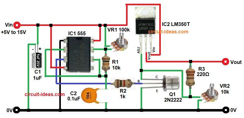
This circuit is for a high power pulse generator which uses 555 timer IC as a pulse oscillator and IC LM350 regulator which gives high current output.
IC 555 can handle high current up to 3A and gives small output current and IC LM350 provides output current upto 3A.
Therefore, this 3A PWM Power Generator Circuit with IC 555 and LM350 is good for motor control, LED power control, heater control and DC load testing.
Input voltage of this circuit is 5V to 15V and output voltage and pulse width both is adjustable, so this is an flexible and useful circuit.
Circuit Working:
Parts List:
| Components | Specification | Quantity |
| Resistors (All resistors are 1/4 watt) | 10k, 1k, 220Ω | 1 each |
| Potentiometer 100k, 10k | 1 each | |
| Capacitors | Electrolytic 1uF 25V | 1 each |
| Ceramic 0.1uF | 1 | |
| Semiconductors | IC 555 timer, IC LM350T | 1 each |
| Transistor 2N2222 | 1 |
First, 555 IC work as astable multivibrator as it generate square wave pulses continuously.
VR1 and timing capacitor control frequency and duty cycle and therefore, pulse width can change.
Pin 3 of 555 give output pulses and this output go through R2 to transistor Q1 base.
When output is HIGH then Q1 turn ON and when output is LOW then Q1 turns OFF.
Q1 control adjustment pin of LM350 and therefore, output voltage change according to pulse.
LM350 is high current adjustable regulator which can supply up to 3A current and thus, high power load can connect at output.
R3 and VR2 set output voltage level, because LM350 follow formula:
Vout = 1.25 (1 + R2 / R1) + Iadj R2
So output is adjustable by VR2 and therefore, this circuit produce high current PWM output.
Note:
Vout is always lower than Vin by about 2V to 3V and this is called dropout voltage.
So practical formula is:
Maximum Vout approx = Vin – 2V (typical)
So let us now calculate for our input range:
If Vin = 5V
Maximum Vout approx = 5V – 2V
Vout approx 3V
So with 5V input the output can be around 2.5V to 3V maximum.
If Vin = 12V
Maximum Vout approx = 12V – 2V
Vout approx 10V
If Vin = 15V
Maximum Vout approx = 15V – 2V
Vout approx 13V
So in short, if Vin = 5V to 15V
Then Vout adjustable from approx 1.25V up to:
3V (when Vin = 5V)
10V (when Vin = 12V)
13V (when Vin = 15V)
How to Build:
To build a 3A PWM Power Generator Circuit with IC 555 and LM350 follow the below connection steps:
- Start the circuit first by collecting all the parts.
- Then start with IC1 555 Timer.
- Pin 1 connect to GND
- Pin 2 join with pin 6 and connect to timing capacitor C1 and R1.
- Pin 3 output to R2 and transistor base Q1.
- Pin 4 and pin 8 connect to Vcc.
- Pin 7 connect between VR1 and resistor R1.
- Then start with IC2 LM350.
- Pin 1 Adjust connect to collector of transistor Q1.
- Pin 2 Input connect to input Vin 5V to 15V.
- Pin 3 output connect to Vout of the circuit.
- Then start with Q1 2N2222 Transistor.
- Emitter pin connect to ground.
- Collector pin connect to LM350 adjust pin.
- Base pin connect to pin 3 of IC1 through resistor R2.
- Connect capacitor C1 positive end from Vin and negative end to GND of the circuit.
- Lastly, connect resistor R3 and VR1 in series from Vout and GND.
Important Notes:
- Use heat sink for LM350, because high current produce heat.
- Use proper filter capacitor at input because this reduce noise.
- If load current is more than 1A then use thick PCB tracks.
Conclusion:
This 3A PWM Power Generator Circuit with IC 555 and LM350 is simple, easy and powerful project.
It combines with 555 timer with LM350 regulator which can handle high current up to 3A.
Frequency and output both are adjustable, so it is flexible for many power control applications.
With proper heat sink and good wiring, circuit work stable and reliable.
Thus, this design is good choice for hobby and project work.
Leave a Reply