IC 555 is used in easy circuit.
Make both plus and minus voltage from one 3V source like two AA battery.
It is useful for 3V to 9V Dual Power Supply Circuit.
555 work as astable multivibrator in circuit.
It make square wave again and again on output pin 3.
Outside resistors and capacitors control how fast it oscillate.
Circuit Working:
Parts List:
| Category | Description | Quantity |
|---|---|---|
| Resistors | 1k 1/4 watt | 1 |
| 10k 1/4 watt | 1 | |
| Capacitors | Ceramic 0.01μF | 1 |
| Ceramic 470pF | 1 | |
| Electrolytic 10μF 25V | 2 | |
| Electrolytic 4.7μF 25V | 2 | |
| Semiconductors | IC 555 | 1 |
| Diode 1N4007 | 4 |
This circuit make two voltages: +9V and -9V from small 3V power like some batteries.
It uses special chip called IC 555.
IC 555 is like heart and it beat in regular way.
In this circuit IC 555 keep switching fast and make square wave signal.
One capacitor, two resistors and control pin decide how fast it switches.
Square wave from IC 555 has both positive and negative parts.
Circuit use two filters one for each diode and capacitor.
Positive filter give +9V by passing only positive part.
Negative filter give -9V by passing only negative part.
Capacitors help smooth the voltage to make it stable.
IC 555 is 8 pin DIP chip and is famous for stable timing and oscillation.
It can run on 3V to 12V power and is so very flexible.
In this circuit IC 555 is in astable mode.
Pins 2 and 6 are joined inside chip for this.
Because of setup IC work nonstop like free running multivibrator.
Capacitor C1 is big part in setting oscillation speed.
C1 charge through R1 and R2 but discharge only through R2.
R1 and R2 set duty cycle which is how long output stay high in each cycle.
In astable mode C1 charge to ⅔ Vcc and discharge to ⅓ Vcc.
IC uses these points to switch output high and low.
IC 555 formula:
Time period (T) = 0.693 × (RA + 2RB) × C
Frequency (f) = 1.44 / ((RA + 2RB) × C)
Formulas:
To make astable multivibrator with IC 555 and two power supplies 3V to 9V use this formula:
Frequency (f):
f = 1.44 / (R1 + 2 × R2) × C1
where:
- f is the frequency in Hz
- R1 and R2 are the resistors in ohms Ω
- C1 is the capacitor in farads F
This setup works in astable mode.
IC 555 keep switching and make square wave.
By changing R1, R2 and C1 we can get the frequency we want.
Use this formula to design circuit that runs from 3V to 9V power.
How to Build:
To build a 3V to 9V Dual Power Supply Circuit follow the below mentioned steps for connections:
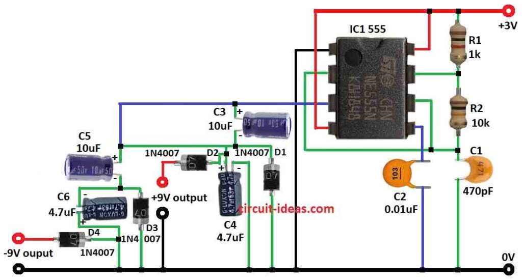
- Gather all parts like in circuit diagram.
- Connect pin 1 of IC 555 to ground.
- Connect pin 2 to pin 6.
- Connect C3, C4 and diode D1, D2 from pin 3 to ground to make +9V output.
- Connect C5, C6 and diode D3, D4 from pin 3 to ground to make -9V output.
- Connect pin 4 to +3V supply.
- Connect pin 5 to ground using capacitor C2.
- Connect pin 6 to pin 2 again.
- Connect pin 7 to +3V supply using resistor R1.
- Connect resistor R2 between pin 7 and pin 6.
- Connect capacitor C1 from pin 2 and 6 to ground.
- Connect pin 8 to +3V supply.
Safety Notes:
- Work in good light so we can see parts clearly.
- Use wire cutter and soldering iron safely.
- Try to keep someone near in case of problem.
- Before turning ON the circuit, double check all wires match the circuit diagram.
Conclusion:
This 3V to 9V Dual Power Supply Circuit using IC 555 give both +9V and -9V from one small 3V source.
It is easy and useful for small projects needing both positive and negative voltage.
References:
How can I power a 3.3v circuit with a 9V power supply and two AA batteries?