Tall buildings, towers and other high structures require warning lights to ensure aircraft safety and a red 230V LED bulb typically serves as the warning lamp.
This LDR Based Aircraft Warning Signal Light Circuit automatically switches ON the bulb in night and switch OFF in day, also it uses LDR sensor, relay and small power supply and this saves electricity and reduce manual operation.
Circuit Working:
Parts List:
| Components | Values | Quantity |
|---|---|---|
| Resistors | 47k 1/4 watt | 1 |
| Potentiometer 200k | 1 | |
| LDR | 1 | |
| Capacitors | Electrolytic 1000µF 25V | 1 |
| Electrolytic 470µF 25V | 1 | |
| Semiconductors | Transistor BC547 | 1 |
| Diode 1N4007 | 1 | |
| Bridge Rectifier 1N4007 | 4 | |
| Transformer 230V AC 12V 500mA | 1 | |
| SPDT Relay 12V | 1 | |
| Red LED Bulb 230V | 1 |
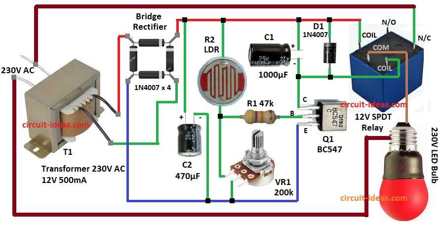
In the above circuit 230V AC is step down to 12V AC by transformer T1 and then bridge rectifier change AC to DC and capacitor C2 filter DC and gives supply to control part.
LDR is main sensor in the circuit and when mains is ON the bulb glows and light fall on LDR and its resistance goes low with more voltage goes to base of transistor Q1 and so Q1 turns ON.
Then relay activates and bulb switches OFF and now no light is on LDR as its resistance goes high and base voltage drops with Q1 turns OFF.
So relay deactivate and bulb glow again and this cycle repeats and bulb keep flashing; after that, capacitor C1 across relay keep relay ON little longer so bulb stays OFF for some extra time.
Now fix LDR near bulb so light falls on it and after wiring, power ON the circuit and adjust pot VR1 until bulb start flashing.
Reminder: Be careful some parts have high voltage and can give shock.
How to Build:
To build a LDR Based Aircraft Warning Signal Light Circuit follow the below steps for connection:
- First, gather all the circuit parts as shown in diagram above.
- Next, transformer T1 connects to 230V mains and secondary 12V AC goes to bridge rectifier.
- Then bridge rectifier output connects to filter capacitor C2 positive.
- After that, LDR one end goes to positive supply and other end to junction of R1 and VR1 and then R1 47k resistor connects from base of Q1 transistor.
- The circuit also connects one terminal of the 200kΩ potentiometer VR1 to the voltage divider network with the LDR, while the other terminal connects to ground GND.
- Also, Q1 collector connect to one end of relay coil and other end of coil goes to +12V.
- Further, connect capacitor and diode D1 in series as shown in circuit diagram
- Finally, relay common pin connects to 230V supply with N/C pin to bulb and other end of bulb to T1 transformer of 230V AC
Conclusion:
Overall, this LDR-based Aircraft Warning Signal Light Circuit provides a simple and low cost solution for aircraft warning lamps.
The circuit operates automatically during both day and night without requiring manual switching.”
Users can adjust the sensitivity with a potentiometer and the relay provides isolation so the circuit can safely control a 230V bulb.
Furthermore, this circuit is highly useful for towers, buildings, chimneys, and other tall structures.
Leave a Reply