Power supply is the heart of any electronic circuit, without stable voltage the circuit will fail; sometimes 7805 IC is not enough and also sometimes current requirement is higher, therefore, discrete regulator is useful.
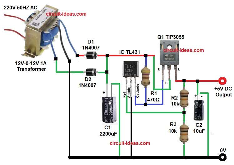
This 5V 0.5A Regulated Power Supply Circuit gives 5V output at 0.5A current and it uses TIP3055 transistor and IC TL431 reference.
The circuit is simple and with low cost, making it suitable for beginners, so lets go through its working and construction process.
Circuit Working:
Parts List:
| Components | Values | Quantity |
|---|---|---|
| Resistors | 470Ω | 1 |
| 10k | 2 | |
| Capacitors | Electrolytic 2200uF 25V, 10uF 25V | 1 each |
| Semiconductors | IC TL431 | 1 |
| Transistor TIP3055 | 1 | |
| Diodes 1N4007 | 2 | |
| Transformer 220V 50HZ AC to 12V-0-12V 1A | 1 | |
| Power Supply Output 5V DC 0.5A | 1 | |
| Heat Sink For TIP3055 Transistor | 1 |
First of all, the circuit takes 220V AC input, then the transformer steps down the voltage and produces 12V AC on both sides.
The center tap connects to ground and next, diodes D1 and D2 form a full-wave rectifier, and these diodes convert AC into pulsating DC.
Then capacitor C1 filters the DC, so voltage becomes smooth DC and then this DC is around 16 to 18 volts.
After that resistor R1 feeds current to TL431 and this TL431 works like adjustable Zener and it compares output voltage with internal reference.
Meanwhile, R2 and R3 form voltage divider and this divider sets output voltage to 5V and if output increases then TL431 conducts more and then the base current of TIP3055 reduces; so output voltage comes down;
Similarly, if output drops then TL431 conducts less and then base current increases, so output rises again, in this way the regulation happens and hence output stays at 5V.
Finally, capacitor C2 filters output noise and thus clean 5V DC is available.
Formula with Calculation:
Output voltage formula mentioned below:
Vout = Vref × (1 + R2 / R3)
As per circuit diagram values.
- R2 value is 10k
- R3 value is also 10k
Now calculation is as follows:
Vout = 2.5 × (1 + 10k / 10k)
10k divided by 10k gives 1.
So equation becomes:
Vout = 2.5 × (1 + 1)
Vout = 2.5 × 2
Vout = 5V
Final output voltage is 5V.
How to Build:
To build a 5V 0.5A Regulated Power Supply Circuit follow the below steps for connection:
- First, collect all components as shown in circuit diagram.
- Next, transformer primary connect to 220V AC supply, transformer secondary has three wires: one is 12V, one is center tap and one more is 12V.
- Now connect diode D1 anode goes to one 12V wire and connect diode D2 next anode of D2 goes to other 12V wire.
- Join cathode of D1 and cathode of D2 together and after that, connect capacitor C1.
- Also, positive of C1 goes to joined diode cathode point and negative of C1 goes to center tap ground.
- Now connect resistor R1 with one side of R1 goes to DC positive line and other side goes to reference pin of TL431.
- Then connect TL431 IC with pin 1 reference connects to junction point of R2 and R3.
- Further, pin 2 anode connects to ground and pin 3 cathode connects to base resistor and also to R1.
- Next, connect transistor Q1 2N3055 with base of Q1 connects to TL431 cathode, emitter of Q1 connects to output 5V line and collector of Q1 connects to DC input line.
- Now connect resistor R2 and R3 and both resistors connect in series, with top end of R2 goes to 5V output and bottom end of R3 goes to ground.
- Finally connect capacitor C2 with positive of C2 goes to 5V output and negative of C2 goes to ground.
Note:
- Use a good and a proper heat sink for Transistor TIP3055.
Conclusion:
To conclude, this 5V 0.5A Regulated Power Supply Circuit is very useful project for one to try for, as it gives good current and is stable and reliable and also, parts are easily available and circuit is easy to build.
Hence, it is good for hobby projects and moreover, it can replace IC regulators and with proper heat sink it works for longer time.
Leave a Reply