The LM2596HV is a high-voltage adjustable step-down switching regulator IC which works similar to the standard LM2596, but it supports higher input voltage up to 60V.
Because of this, it is suitable for transformer-based power supply circuits, industrial DC lines, battery charging systems and adjustable bench power supplies.
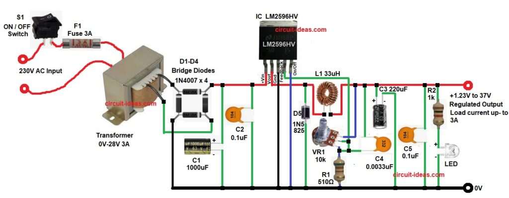
In this LM2596HV Adjustable DC Voltage Regulator Circuit, AC input first converts into DC using bridge rectifier diodes, after that the LM2596HV regulates the voltage and provides adjustable DC output from 1.23V up to 37V with load current up to 3A.
Circuit Working:
Parts List:
| Components | Values | Quantity |
|---|---|---|
| Resistors | 510Ω, 1k 1/4 watts | 1 each |
| Potentiometer 10k | 1 | |
| Capacitors | Electrolytic 1000uF 63V, 220uF 63V | 1 each |
| Ceramic 0.1uF 100V | 2 | |
| Ceramic 0.0033uF 50V | 1 | |
| Semiconductors | IC LM2596HV Adjustable | 1 |
| Bridge Rectifier Diodes 1N4007 1000V, 1A | 4 | |
| Schottky Diode SS34 or 1N5825 | 1 | |
| 8mm White LED | 1 | |
| Inductor / Coil 33uH | 1 | |
| Transformer 230V Primary and 0V-28V 3A secondary | 1 | |
| Fuse 3A | 1 | |
| ON / OFF Switch | 1 |
In the above circuit 230V AC mains goes through the ON/OFF switch and fuse and this gives power control and circuit protection.
After this, supply enters the transformer primary winding and the transformer steps down voltage to 28V AC and then this AC goes to the bridge rectifier section.
Next, capacitor C1 smooths the rectified voltage and reduces ripple and capacitor C2 removes high-frequency noise.
After that, the DC voltage goes to pin 1 of LM2596HV and this is the input pin of the IC.
Now the switching section starts and inside the IC an internal switch turns ON and OFF at around 150 kHz, as this fast switching controls the energy flow through inductor L1.
When the internal switch turns ON the current flows through the inductor and the inductor stores energy in its magnetic field.
When the switch turns OFF the inductor releases the stored energy through diode D5 and then it supplies current to the output, because of this action the output becomes smooth DC voltage.
VR1 works as voltage adjustment potentiometer, and by rotating VR1 the feedback voltage changes, because of this the output voltage also changes.
Capacitors C3 and C5 filter the output and reduce ripple and LED with resistor R2 works as output power indicator.
LM2596HV regulates the voltage properly as it also supports higher input voltage up to 60V.
How to Build:
To build a LM2596HV Adjustable DC Voltage Regulator Circuit follow the below connection steps:
- Gather all the parts as per the circuit diagram above.
- Next, start with transformer primary which is connected with switch and fuse.
- Then, transformer secondary is connected to bridge diodes two ends.
- Bridge diodes remaining two pins one goes to ground and other goes to IC pin 1.
- After this connect capacitor C1 and capacitor C2 at DC input line.
- Next, pin 2 goes to cathode of diode D5 and inductor L1 one end.
- Pin 3 of IC goes to ground.
- Pin 4 is the feedback pin and connect this pin to voltage divider network with VR1, R1 and capacitor C5.
- Then take last pin 5 ON/OFF which also goes to ground.
- After that connect diode D5 cathode end to pin 2 of IC and anode goes to ground.
- Then take L1 coil and connect it between cathode of D5 and VR1 pot upper pin end.
- Connect VR1 middle pin to pin 4 of IC and lower pin connect to one end of resistor R1 and other end of R1 goes to ground.
- Then connect capacitor C4 at output line end and other end junction of R1 and VR1.
- Connect capacitor C3 and C5 in parallel from output end and to ground.
- And lastly, connect resistor R2 and LED from output end and ground.
Conclusion:
This LM2596HV Adjustable DC Voltage Regulator Circuit is a simple and efficient power supply project which gives variable DC output with good current capability up to 3A.
The circuit is easy to build and works well for many electronics projects and also because it uses switching method the heat loss stays much lower than linear regulators.
With correct inductor, diode and capacitor selection, this circuit provides stable and reliable output voltage.
Leave a Reply