This Simple 2 LED Battery Status Indicator Circuit work like gas meter but for battery, as it uses LED lights to tell how much power battery still have.
One light mean battery is full another light mean half power and last light mean time to charge.
Also, it use small parts like resistors, Zener diodes and transistors to check battery voltage and turn ON the lights.
so we can always see when to charge and keep our device working.
Circuit Working:
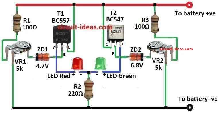
Parts List:
| Components | Values | Quantity |
|---|---|---|
| Resistors | 100Ω | 2 |
| 220Ω | 1 | |
| Preset 5k | 2 | |
| Semiconductors | Transistors BC557, BC547 | 2 each |
| Zener diode 4.7V 400mW, 6.8V 400mW | 1 each | |
| LEDs Red and Green 5mm 20mA | 1 each |
If LED light always stay ON in battery device like emergency lamp it will use battery even when not using the lamp.
Hence, this make battery lose power slowly because LED need around 2 volts to work.
So people keep charging battery again and again to keep it full, but this circuit fixes that problem it only turn ON LED two times:
When battery is too full means overcharge or too low means overdischarge, this circuit use Zener diodes and work like a voltage switch.
Furthermore, it uses one bicolor LED in which one light show red and the other one show green to show two states.
ZD1 Zener diode and T1 PNP transistor show when battery is almost empty and when battery voltage is more than 5V ZD1 works and stops T1 so red LED goes OFF.
But if battery goes below 5V then ZD1 stop working and T1 turns ON and red LED turn ON and this mean battery is going empty.
Also, ZD2 and the T2 NPN transistor indicate when the battery becomes overcharged.
When battery is under 6.8V ZD2 does not work and T2 is OFF then green LED goes OFF, but if battery goes more than 7V then ZD2 and T2 turn ON and green LED turns ON.
This means the battery is overcharged.
Therefore, when the battery voltage stays between 5V and 7V and the LED turns ON, the circuit saves power.
To set this circuit correct, we need power supply where we can change.
First give 5V and adjust VR1 so red LED turn ON and green LED stay OFF and then give 7V and adjust VR2 so green LED turn ON and red LED stay OFF and at 6V both LED must be OFF.
Formulas:
This formula calculates the resistor divider output voltage, circuits such as battery level checkers use it to find the output voltage (Vout):
Vout = (Rb / (Ra + Rb)) × Vin
here,
- Vout is the voltage where LED just start to glow and should be near 3 volts.
In our circuit:
- For red LED Rb is VR1 and Ra is R1.
- For green LED Rb is VR2 and Ra is R3.
This formula help to set when LED will turn ON.
How to Build:
To build a Simple Battery Status Indicator Circuit follow the below mentioned steps:
- First, connect Zener diode ZD1 and transistor T1 for low battery overdischarge LED.
- Next, connect anode of ZD1 to base of T1 and connect cathode of ZD1 to (+) side of battery.
- After that, connect emitter of T1 to (–) side of battery, connect collector of T1 to red side of bicolor LED.
- Now connect Zener diode ZD2 and transistor T2 for overcharge LED:
- Then connect anode of ZD2 to base of T2 and connect cathode of ZD2 to (+) side of battery.
- Also, connect emitter of T2 to (–) side of battery and connect collector of T2 to green side of bicolor LED.
Connect variable resistors:
- Connect VR1 between base of T1 and one side of battery and connect VR2 between base of T2 and one side of battery.
- Add resistors to limit current for LEDs, put one resistor in line with red LED and put another resistor in line with green LED.
- Connect other pin of bicolor LED with common pin to ( +) side of battery.
Calibration (setting it right):
- Give 5V to circuit and turn VR1 until red LED turns ON.
- Now give 7V and turn VR2 until green LED turns ON and set voltage to 6V and now both LEDs should be OFF.
Note:
- Use proper resistor values to stop too much current going to LEDs and check LED datasheet for this.
Conclusion:
Simple 2 LED Battery Status Indicator Circuit is helpful circuit that uses LED lights to show how much charge is in battery; also it checks battery voltage and show if battery is full, low or need charging.
Finally, this help people know battery status and use power in better way.
Leave a Reply